C. Accessories
ELECTRONIC AIR CLEANER (EAC)
Spring loaded terminals (EAC-1 and EAC-2) are provided for
EAC connection. (See Fig. 15.) The terminals are energized with
115v, 1.0-amp maximum during blower motor operation.
HUMIDIFIER (HUM)
Screw terminals (HUM and C
OM 24v) are provided for 24-v
humidifier connection. The terminals are energized with 24v,
0.5-amp maximum when the gas valve is energized.
WARNING: Do not connect furnace control HUM ter-
minal to HUM (humidifier) terminal on Thermidistat,
Zone Controller, or similar device. See Thermidistat,
Zone Controller, thermostat, or controller manufacturer’s
instructions for proper connection. A failure to follow this
warning could result in fire.
NOTE: A field-supplied, 115-v controlled relay connected to
EAC terminals may be added, if humidifier operation is desired
during blower operation.
D. Venting
Refer to the enclosed Installation Instructions, (Vent Tables For 1-
and 2-Stage Category I Fan-Assisted Furnaces) for quick, easy
reference and national or local code such as NFGC in the United
States, or NSCNGPIC in Canada, for proper vent sizing and
installation requirements.
After fully assembling the vent connector to the furnace flue collar,
securely fasten the vent connector to the collar with 2 field-
supplied, corrosion-resistant, sheet metal screws located 180
degrees apart and midway up the collar.
The horizontal portion of the venting system shall maintain a
minimum of 1/4-in. upward slope per linear ft and it shall be
rigidly supported every 5 ft or less with hangers or straps to ensure
that there will be no movement after installation.
START-UP, ADJUSTMENT, AND SAFETY CHECK
I. GENERAL
The furnace must have a 115-v power supply properly connected
and grounded. Correct polarity must be maintained to enable gas
heating operation.
The gas service pressure must not exceed 0.5 psig (14-in. wc), and
no less than 0.16 psig (4.5-in. wc).
Thermostat wire connections at R and W/W1 are the minimum
required for gas heating operation. W2 must be connected for
2-stage heating thermostats. Y/Y2 and G are required to be
connected to the furnace for cooling and heat pumps. G is required
for continuous-fan. C
OM 24v is required for some clock thermo-
stats. These connections must be made at the 24-v terminal block
on furnace control. (See Fig. 15.) O is required for heat pumps
only. Y1 is required for 2-stage cooling and 2-stage heat pumps.
The O and Y1 connectors must be made to the ICM2+ furnace’s
orange and blue leads, flagged ″O″ and ″Y1,″ respectively.
This furnace can be installed with either a single-stage heating or
a 2-stage heating thermostat.
For single-stage thermostats, connect thermostat R to W/W1 at the
furnace control terminal block. (See Fig. 16.) For single-stage
thermostats, the control will determine, based on length of previ-
ous heating on and off cycles, when to operate in low- and
high-stage for optimum comfort. Setup switch-2 (SW-2) must be
in the factory-shipped OFF position. See Fig. 18 and Tables 6 and
7 for setup switch information.
If a 2-stage heating thermostat is to be used, move SW-2 to the ON
position at end of furnace installation. This overrides built-in
control process for selecting high- and low-stage and allows the
2-stage thermostat to select gas heating modes. The W2 from
thermostat must be connected to W2 on control terminal block.
(See Fig. 17.)
CAUTION: This furnace is equipped with a manual
reset limit switch in the gas control area. The switch will
open and shut off power to the gas valve if a flame rollout
or overheating condition occurs in the gas control area.
DO NOT bypass the switch. Correct inadequate
combustion-air supply, component failure, or restricted
flue gas passageway before resetting the switch.
Before operating furnace, check each manual reset switch for
continuity. If necessary, press and release the button to reset
switch. The blower compartment door must be in place to
complete the 115-v circuit to furnace.
TABLE 5—ELECTRICAL DATA
UNIT SIZE
VOLTS—
HERTZ—
PHASE
OPERATING
VOLTAGE RANGE
MAX
UNIT
AMPS
MIN
WIRE
GAGE
MAX WIRE
LENGTH (FT)‡
MAX FUSE OR
CKT BKR AMPS†
Max* Min*
036060 115—60—1 127 104 10.1 14 36 15
048080 115—60—1 127 104 10.6 14 34 15
060100 115—60—1 127 104 12.6 14 29 15
060120 115—60—1 127 104 13.9 14 26 15
* Permissible limits of the voltage range at which the unit will operate satisfactorily.
† Time-delay fuse is recommended.
‡ Length shown is as measured along wire path between unit and service panel for maximum 2 percent voltage drop.
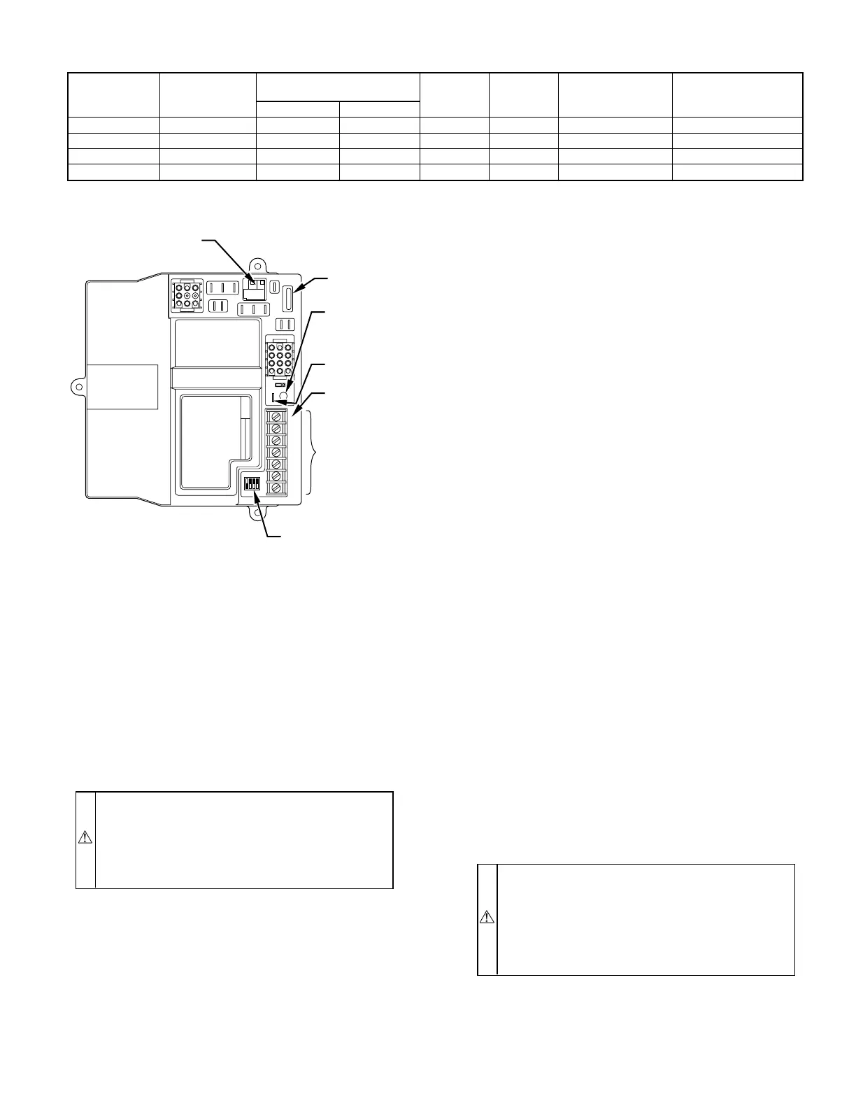
Fig. 15—Furnace Control
A01370
123
456
78 9
PR2
L2
COM
PR1
L1
HI-COOL
HI-GAS
-HEAT
LO-GAS
-HEAT
PARK
3
FU1
SEC-1
SEC-2
1
123
456
7
8
9
10 11 12
M S
TWIN
TEST
LED
GRY/Y2W/W1COM
24 V
W2
1
ON
OFF
1234
FURNACE AND
BLOWER OFF DELAY
SETUP SWITCHES
24-VOLT
THERMOSTAT
TERMINALS
EAC - ELECTRONIC
AIR CLEANER
(115-VAC 1 AMP MAX)
3-AMP
FUSE
LED -
DIAGNOSTIC
LIGHT
TWIN / TEST
TERMINAL
HUM -
HUMIDIFIER
(24-VAC 0.5
AMP MAX)
HUM
—11—
→
→