in alcoves, attics, basements, closets, crawlspaces, or utility rooms.
The design of this furnace line is not C.S.A. (A.G.A. and C.G.A.)
design-certified for installation in mobile homes, recreation ve-
hicles, or outdoors.
These instructions cover minimum requirements and conform to
existing national standards and safety codes. In some instances,
these instructions exceed certain local codes and ordinances,
especially those that may not have kept up with changing residen-
tial construction practices. We require these instructions as a
minimum for a safe installation.
CAUTION: Application of this furnace should be in-
doors with special attention given to vent sizing and
material, gas input rate, air temperature rise, and unit
sizing. Improper installation or misapplication of the
furnace can require excessive servicing or cause prema-
ture component failure.
To aid in installation, troubleshooting, and service, a status code
label is located on the blower compartment door. This label
explains how to use the LED status indicator on the furnace control
which is viewed through the sight glass on the door.
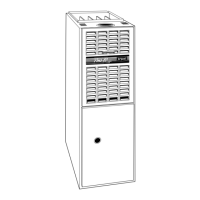
NOTE: These furnaces are designed for a minimum continuous
return-air temperature of 60°F or intermittent operation down to
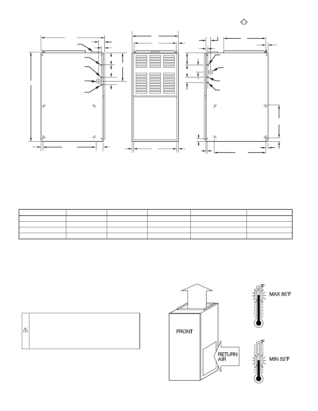
Fig. 1—Dimensional Drawing
TABLE 1—DIMENSIONS (IN.)
UNIT SIZE A D E FLUE COLLAR SHIP. WT
036060 14-3/16 12-9/16 12-11/16 4 132
048080 21 19-3/8 19-1/2 4 156
060100 14-1/2 22-7/8 12 4 183
060120 24-1/2 22-7/8 23 5 194
A00210
A
D
13
⁄16″
E
11
⁄16″
11
⁄16″
28
1
⁄2″
39
7
⁄8″
24
5
⁄16″
11
⁄16″
3″
2
1
⁄16″
1″
12
5
⁄16″
5
3
⁄8″
5
13
⁄16″
2
3
⁄8″
AIR INLET
7
⁄8-IN. DIA HOLE
POWER ENTRY
7
⁄8-IN. DIA
ACCESSORY
1
3
⁄4-IN. DIA HOLE
GAS ENTRY
1
⁄2-IN. DIA HOLE
THERMOSTAT
WIRE ENTRY
SIDE INLET
VENT CONN
1. Two additional
7
⁄8-in. dia holes are located in the top plate.
2. Minimum return-air openings at furnace, based on metal duct. If flex duct is used,
see flex duct manufacturer's recommendations for equivalent diameters.
a. For 800 CFM–16-in. round or 14
1
⁄2 x 12-in. rectangle.
b. For 1200 CFM–20-in. round or 14
1
⁄2 x 19
1
⁄2-in. rectangle.
c. For 1600 CFM–22-in. round or 14
1
⁄2 x 23
1
⁄4-in. rectangle.
d. For airflow requirements above 1800 CFM, see Air Delivery table in Product Data literature for specific
use of single side inlets. The use of both side inlets, a combination of 1 side and the bottom, or the
bottom only will ensure adequate return air openings for airflow requirements above 1800 CFM.
NOTES:
5
3
⁄8″
5
13
⁄16″
2
3
⁄8″
2
11
⁄16″
1″
2
1
⁄16″
19″
13
⁄16″
7
⁄8-IN. DIA
POWER ENTRY
AIRFLOW
OUTLET
1
1
⁄2-IN. DIA
R.H. GAS ENTRY
7
⁄8-IN. DIA ACCESSORY
1
⁄2-IN. DIA THERMOSTAT
WIRE ENTRY
SIDE INLET
14
1
⁄2″
1″
23
1
⁄4″
SIDE RETURN
DUCT LOCATION
1
1
⁄4″
TYP 1″
5
⁄8″
TYP
Fig. 2—Return-Air Temperature
A93042
—2—