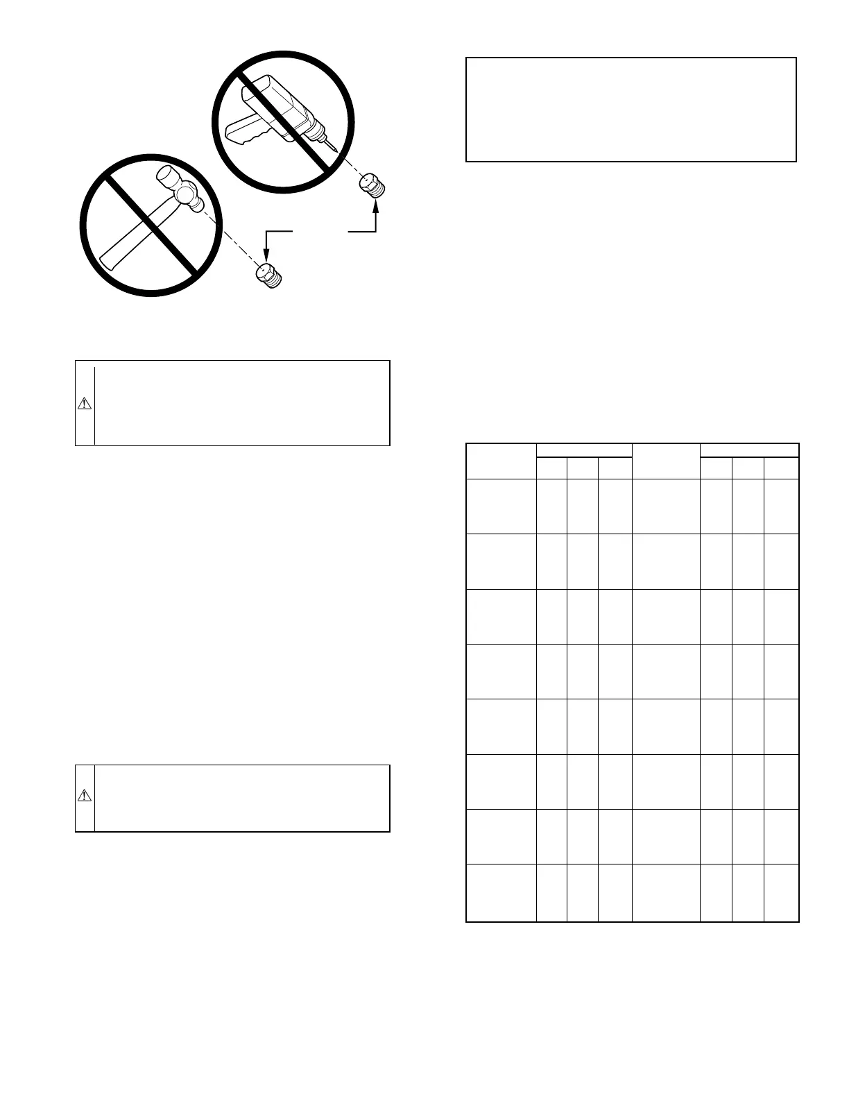
CAUTION: DO NOT redrill orifices. Improper drilling
(burrs, out-of-round holes, etc.) can cause excessive
burner noise and misdirection of burner flames. This can
result in flame impingement of burners and heat exchang-
ers, causing failures. (See Fig. 21.)
g. Check and verify burner orifice size in furnace. NEVER
ASSUME ORIFICE SIZE; ALWAYS CHECK AND
VERIFY.
3. Adjust manifold pressure to obtain input rate.
a. Remove caps that conceal adjustment screws for low-
and high-heat gas valve regulators. (See Fig. 22.)
b. Move setup switch SW-2 on control to ON position. (See
Fig. 18.) This keeps furnace locked in low-heat opera-
tion.
c. Jumper R and W/W1 thermostat connections on control
to start furnace.
d. Turn low-heat adjusting screw (5/64 hex Allen wrench)
counterclockwise (out) to decrease input rate or clock-
wise (in) to increase input rate.
NOTE: DO NOT set low-heat manifold pressure less than 1.3-in.
wc or more than 1.7-in. wc for natural gas. If manifold pressure is
outside this range, change main burner orifices.
CAUTION: DO NOT bottom out gas valve regulator
adjusting screw. This can result in unregulated manifold
pressure and result in excess overfire and heat exchanger
failures.
NOTE: If orifice hole appears damaged or it is suspected to have
been redrilled, check orifice hole with a numbered drill bit of
correct size. Never redrill an orifice. A burr-free and squarely
aligned orifice hole is essential for proper flame characteristics.
e. Move setup switch SW-2 to OFF position after complet-
ing low-heat adjustment.
f. Jumper R and W2 thermostat connections on control
center. (See Fig. 15.) This keeps furnace locked in
high-heat operation.
g. Turn high-heat adjusting screw (5/64 hex Allen wrench)
counterclockwise (out) to decrease input rate or clock-
wise (in) to increase rate.
NOTE: DO NOT set high-heat manifold pressure less than 3.2-in.
wc or more than 3.8-in. wc for natural gas. If manifold pressure is
outside this range, change main burner orifices.
h. When correct input is obtained, replace caps that conceal
gas valve regulator adjustment screws. Main burner
flame should be clear blue, almost transparent. (See Fig.
23.)
i. Remove jumper R to W2.
4. Verify natural gas input rate by clocking gas meter.
a. Calculate high-altitude adjustment (if required).
UNITED STATES
At altitudes above 2000 ft, this furnace has been approved for a 4
percent derate for each 1000 ft above sea level. See Table 13 for
derate multiplier factor and example.
CANADA
At installation altitudes from 2000 to 4500 ft, this furnace must be
derated 10 percent by an authorized Gas Conversion Station or
Dealer. To determine correct input rate for altitude, see example
above and use 0.90 as derate multiplier factor.
b. Check that gas valve adjustment caps are in place for
proper input to be clocked.
Fig. 21—Burner Orifice
A93059
BURNER
ORIFICE
EXAMPLE:
85,000 Btuh furnace installed at 4300 ft.
Furnace Input
Rate at
Sea Level
X
Derate
Multiplier
Factor
=
Furnace Input Rate
at Installation
Altitude
85,000 X 0.82 = 69,700
TABLE 12—GAS RATE (CU FT/HR)
SECONDS
FOR 1
REVOLUTION
SIZE OF TEST DIAL
SECONDS
FOR 1
REVOLUTION
SIZE OF TEST DIAL
1
cu ft
2
cu ft
5
cu ft
1
cu ft
2
cu ft
5
cu ft
10
11
12
13
14
360
327
300
277
257
720
655
600
500
514
1800
1636
1500
1385
1286
50
51
52
53
54
72
71
69
68
67
144
141
138
136
133
360
355
346
340
333
15
16
17
18
19
240
225
212
200
189
480
450
424
400
379
1200
1125
1059
1000
947
55
56
57
58
59
65
64
63
62
61
131
129
126
124
122
327
321
316
310
305
20
21
22
23
24
180
171
164
157
150
360
343
327
313
300
900
857
818
783
750
60
62
64
66
68
60
58
56
54
53
120
116
112
109
106
300
290
281
273
265
25
26
27
28
29
144
138
133
129
124
288
277
267
257
248
720
692
667
643
621
70
72
74
76
78
51
50
48
47
46
103
100
97
95
92
257
250
243
237
231
30
31
32
33
34
120
116
113
109
106
240
232
225
218
212
600
581
563
545
529
80
82
84
86
88
45
44
43
42
41
90
88
86
84
82
225
220
214
209
205
35
36
37
38
39
103
100
97
95
92
206
200
195
198
185
514
500
486
474
462
90
92
94
96
98
40
39
38
38
37
80
78
76
75
74
200
196
192
188
184
40
41
42
43
44
90
88
86
84
82
180
176
172
167
164
450
439
429
419
409
100
102
104
106
108
36
35
35
34
33
72
71
69
68
67
180
178
173
170
167
45
46
47
48
49
80
78
76
75
73
160
157
153
150
147
400
391
383
375
367
110
112
116
120
33
32
31
30
65
64
62
60
164
161
155
150
—23—