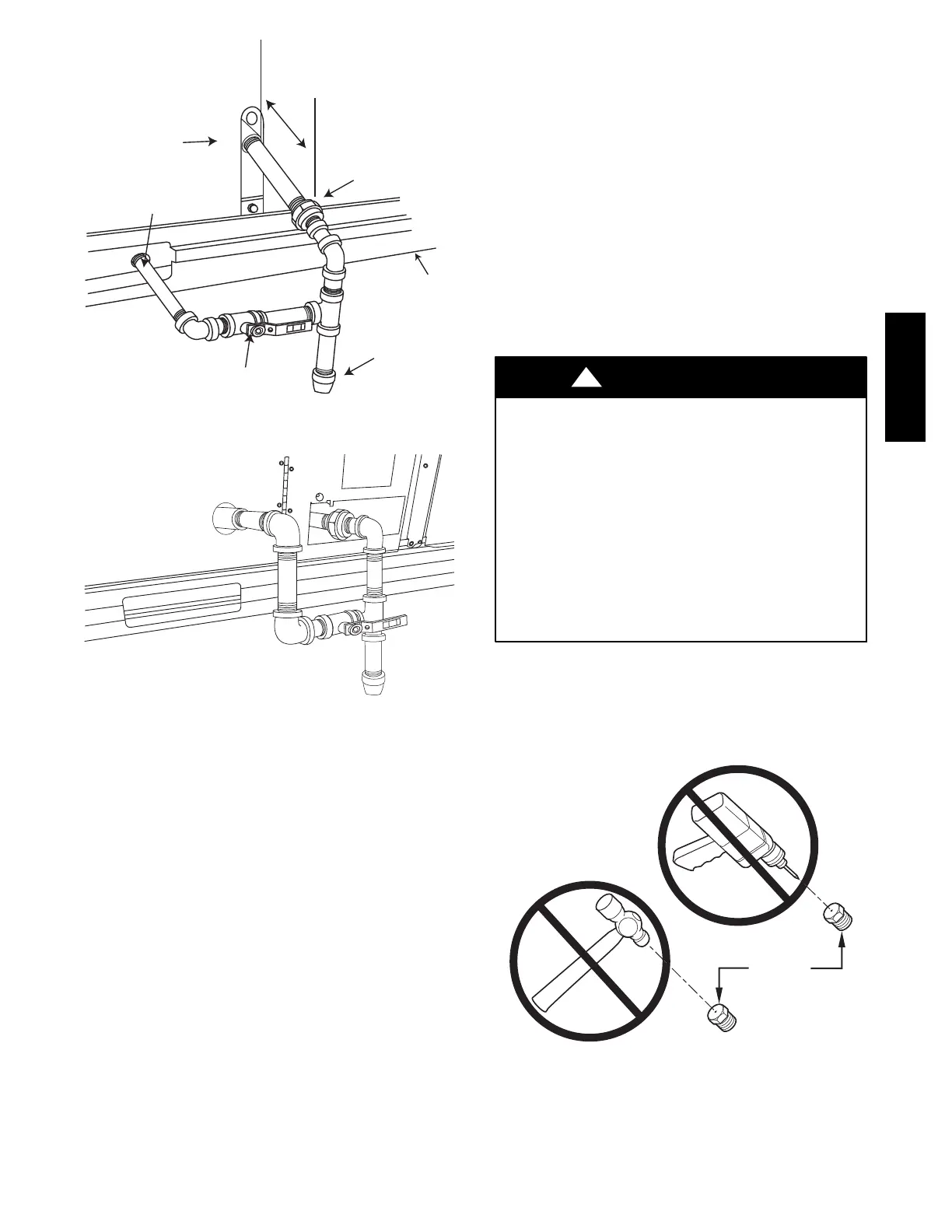
17
Drip
Leg
Shut Off
Valve
Union
Thru-Curb Adapter
Burner
Access
Panel
9” (229mm) min
Unit Base Rail
C07470
Fig. 19 -- Gas Piping
C08018
Fig. 20 -- Gas Piping Thru--Base Connections
When installing the gas supply line, observe local codes
pertainin g to gas pipe installations . Refer to the NFPA
54/ANS I Z223.1 NFGC latest edition (in Canada, CAN /CSA
B149.1). In the absence of local building codes, adhere to
the follow in g pertinent recommendation s :
1. Avoid low spots in long runs of pipe. Grade all pipe
1
/4--in. in every 15 ft (7 mm in every 5 m) to prevent
traps. Grade all horizontal runs downward to risers.
Use risers to connect to heating section and to meter.
2. Protect all segments of piping system against physical
and thermal dam age. Support all piping with appro-
priate straps, hangers, etc. Use a minimum of one
hanger every 6 ft (1.8 m). For pipe sizes larger than
1
/
2
--in., follow recommendations of national codes.
3. Apply joint compound (pipe dope) sparingly and only
to male threads of joint when making pipe c onnec-
tions. Use only pipe dope that is resistant to action of
liquefied petroleum gases as specified by local and/or
national codes. If using PTFE (Teflon) tape, ensure
the material is Double De nsity type and is labele d for
use on gas lines. Apply tape per manufacturer’s in-
structions.
4. Pressure--test all gas piping in accordance with local
and national plumbing and gas codes before connect-
ing piping to unit.
NOTE: Pressure test the gas supply system after the gas
supply piping is connected to the gas valve. T he supply
piping must be disconnected from the gas valve during the
testing of the piping system s when test pressure is in
exce ss of 0.5 psig (3450 Pa). Pressure test the gas supply
piping system at pressures equal to or less than 0.5 psig
(3450 Pa). The unit heating sec tion must be isolated from
the gas piping system by closing the external main manual
shutoff va lve and slightly opening the ground--joint union.
Check for gas leaks at the field--installed and
fact ory--installe d gas lines after all piping connections
have been completed. Use soap--and--water solution (or
method specified by local codes and/or regulations).
FIRE OR EXPLOSION HAZARD
Failure to follow this warning could result in personal
injury, deat h and/or property damage.
S Connect gas pipe to unit using a backup wrench to
avoid damaging gas controls.
S Never purge a gas line i nto a c ombustion chamber.
S Never t est for gas leaks with an open flame. Use a
commercially available soap solution made
specifically for the detection of leaks to check all
connec tions.
S Use proper length of pipe to avoid stress on gas
control manifold.
!
WARNING
NOTE: If orifice hole appears damaged or it is suspected
to have been redrilled, check orifice hole with a numbered
drill bit of correct size. Never redrill an orifice. A
burr--free and squarely aligned orifice hole is essential for
proper flame characteristics.
BURNER
ORIFICE
A93059
Fig. 21 -- Orifice Hole
582J

 Loading...