41
C09302
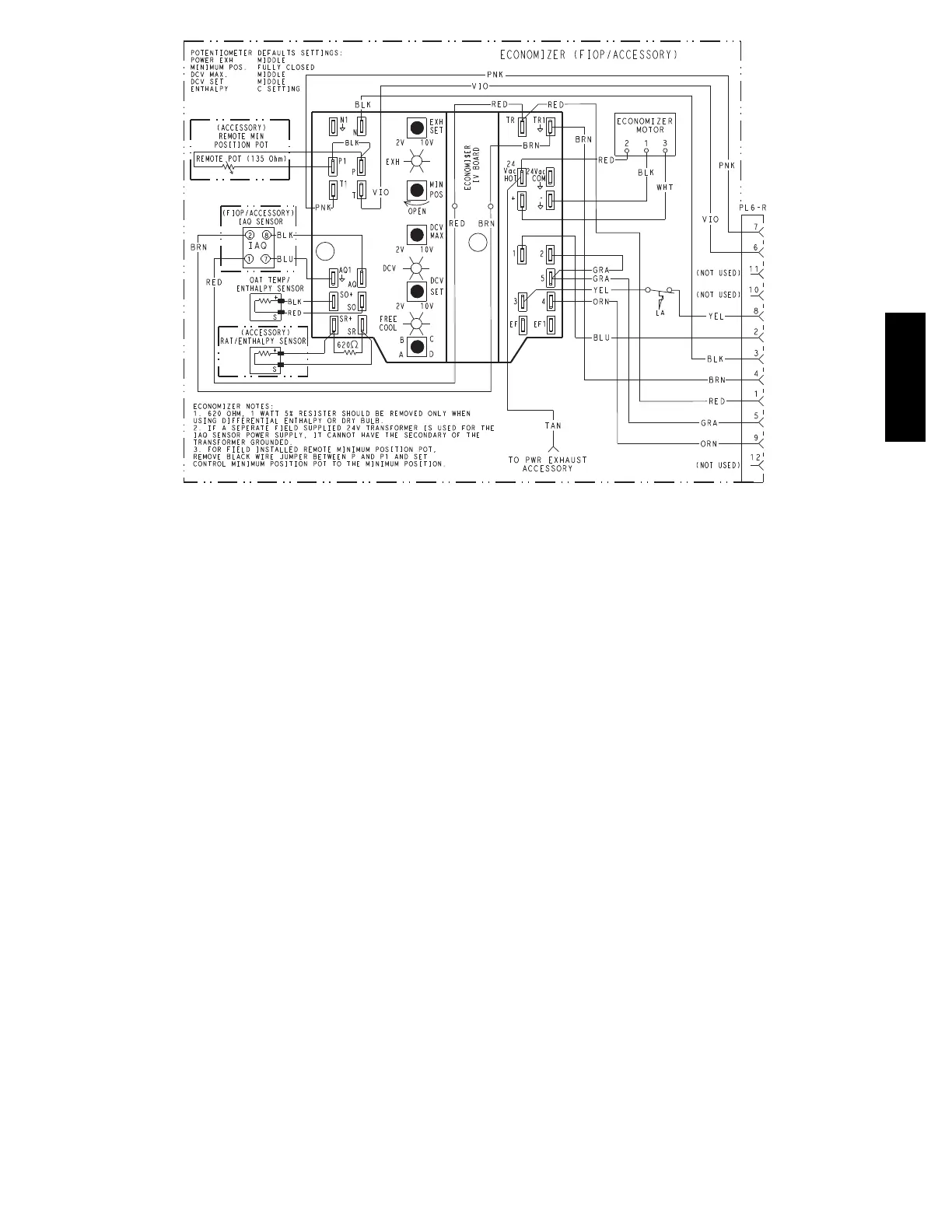
Fig. 61 -- EconoMi$er
R
IV Wiring
Step 14 — Adjust Factory--Installed Options
Smoke Detectors —
Smoke dete ctor(s) will be connected at the Control s
Connect ions Board, at terminals marked “Smoke
Shutdown”. Cut jumper JMP 3 when ready to energize
unit.
EconoMi$er IV Occupancy Switch —
Refer to Fig. 61 for general EconoMi$er IV wiring.
External occupancy control is managed through a
connec tion on the Controls Connections Board.
If external occupancy control is desired, connect a time
clock or remotely controlled switch (closed for Occupied,
open for Unoccupi ed sequence) at terminals marked
OCCUPANCY. Cut jumper JMP 2 to complete the
installation.
Step 15 — Install Accessories
Available accessories include:
Curb
Thru--base connection kit (must be installed before unit
is set on curb)
LP conversion kit
Flue discharge deflector
Manual outside ai r damper
Two--Position motorized outside air damper
EconoMi$e r X (with cont rol)
EconoMi$er IV (wit h control)
EconoMi$e r2 (without c ontrol/for external signal)
Power Exhaust
Differential dry--bulb sensor (EconoMi$er IV)
Outdoor enthalpy sensor
Differential enthalpy sensor
CO
2
sensor
Louvere d hail guard
Motormaster head pressure controls
Phase monitor control
Refer to separate installation instructions for information
on installing these accessories.
Pre --Start and Start--Up
—
This completes the mechanical installation of the unit.
Refer to the unit’s Service Manual for detailed Pre--Start
and Start--Up instructi ons. Download t he latest versions
from HVAC Partners (www.hvacpartners.com).
582J

 Loading...