20
Units Without Factory--Installed
Non--Fused Disconnect —
When installing units, provide a disconnect switch per
NEC (National Electrical Code) of adequate size.
Disconnect sizing data is provi ded on the unit informative
plate. Locate on unit cabinet or within sight of the unit per
national or local codes. Do not cover unit informative
plate if mounting the di sc onnect on the unit cabinet.
All Units —
All field wirin g must comply with NEC and all lo cal codes.
Size wire based on MCA (Minimum Circuit Amps) on th e
unit informative plate. See Fig. 24 and the unit label
diagram for power wiring connections to the unit power
terminal blocks and equipment ground. Maximum wire size
is #2 ga AWG (copper only) per pole on contactors.
Provide a ground--fault and short--circuit over--current
protection device (fuse or breaker) per NEC Article 440
(or local codes). Refer to unit informative data plate for
MOCP (Maximum Over--current Protecti on) device size.
All field wiring must comply with the NEC and local
requirements.
All units except 208/230-v units are factory wired for the
voltage shown on the nameplate. If the 208/230-v unit is
to be connected to a 208-v power supply, the control
transformer must be rewired by moving the black wire
with the
1
/
4
-in. female spade connector from t he 230--v
connec tion and moving it to the 200-v
1
/
4
-in. male
terminal on t he primary side of the transformer. Refer to
unit label diagram for additional informat ion. Field power
wires will be connected line--side pressure lugs on the
power t erminal block or at factory--installed option
non--fused disconnect.
NOTE: Check all factory and field electrical connections
for tightness.
Convenience Outlets —
ELECTRICAL OPERATION HAZARD
Failure to follow this warning could result in personal
injury or death.
Units with convenience out let circuits may use
multiple disconnects. Check convenience outlet for
power status before opening unit for service. Locate
its disconnect switch, if appropriate, and open it.
Lock--out and tag--out this switch, if necessary.
!
WARNING
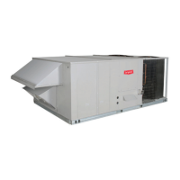
Two types of convenience outlets are offered on 582J
models: Non--powered and unit--powered. Both types
provide a 125--volt GFCI (ground--fault circuit--interrupter)
duplex receptacle rated at 15--A behind a hinged waterproof
access cover, located on the end panel of the unit. S ee Fig.
28.
NOTE: Unit power ed convenience outlets are not
avai lable as factory installe d options for single phase (--J
voltage code) models.
Convenience
Outlet
GFCI
Pwd-CO
Fuse
Switch
Pwd-CO
Transformer
Control Box
Access Panel
C08128
Fig. 28 -- Convenience Outlet Locati on
Installing Weatherproof Cover: A weathe rproof
while-in-use cover for the factory-installed convenience
outlets is now required by UL standards. This c over
cannot be factory-mount ed due its depth; it must be
installed at unit installation. For shipment, the
conveni ence outlet is covered with a blank cover plate.
The weatherproof cover kit i s shipped in the unit’s control
box. The kit include s the hi nged cover, a backing pla te
and gasket.
DISCONNECT ALL POWER TO UNIT AND
CONVENIENCE OUTLET. LOCK--O U T A N D TAG--OU T
ALL POWER.
Remove the blank cover plate a t the c onvenience outlet;
discard the blank cover.
Loosen the two screws at the GFCI duplex outlet, until
approximately
1
/
2
-in (13 mm) under screw heads a re
exposed. Press the gasket over the screw heads. Slip the
backi ng plate over the screw heads at t he keyhole slots
and align with the gasket; tighten the two screws until
snug (do not over-tighten).
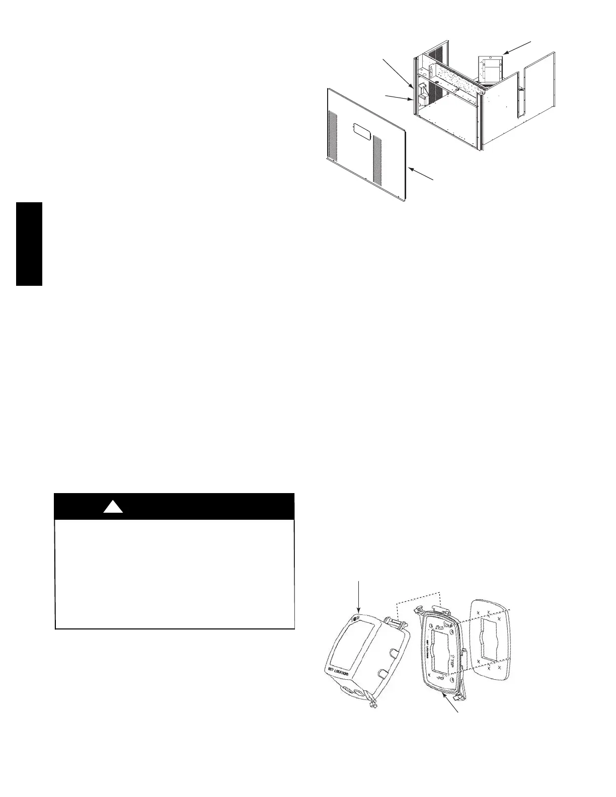
Mount the weatherproof cover to the backing plate as
shown in Fig. 29. Remove two slot fillers in the bottom of
the cover t o permit service tool cords to exit the cover.
Check for full closing and latching.
RECEPTACLE
NOT INCLUDED
COVER – WHILE-IN-USE
WEATHERPROOF
BASE PLATE FOR
GFCI RECEPTACLE
C09022
Fig. 29 -- Weatherproof Cover Installation
582J

 Loading...