8
INSTALLATION
Jobsite Survey
Complete the following checks before installation.
1. Consult local building codes and the NEC (National
Electrical Code) ANSI/NFPA 70 for special installa-
tion requirements.
2. Determine unit location (from project plans) or select
unit location.
3. Check for possible overhead obstructions which may
interfere with unit lifting or rigging.
Step 1 — Plan for Unit Location
Select a locat ion for the unit and its support system (curb
or other) that provide s for the minimum clearances
required for safety. This includes the clearance to
combustible surfaces, unit performance and service access
below, around and above unit a s speci fied in unit
drawings. See Fig. 3.
NOTE: Consider also the effect of adjacent units.
Be sure that uni t is installed such that snow will not block
the combustion intake or flue outlet.
Unit may be installed directly on wood flooring or on
Class A, B, or C roof--covering material when roof c urb is
used.
Do not install unit in an indoor locati on. Do not locate air
inlets near exhaust vents or other sources of contaminated
air. For proper unit ope ration, adequate combustion and
ventilation air must be provided in accordance with
Section 5.3 (Air for Combustion and Ventilation) of the
Nationa l Fuel Gas Code, ANSI Z223.1 (American
Nationa l Standards Institute) and NFPA (National Fire
Protection Association) 54 TIA----54 ----84----1. In Canada,
installation must be in accordance with the CAN1 ---- B149
installati on codes for gas burning applia nces.
Although unit is weatherproof, avoid locations that permit
water from higher level runoff and overhangs to fall onto
the unit.
Locate mechanical draft system flue assembly at least 4 ft
(1.2 m) from any opening through which c ombustion
products could e nter the building, and at least 4 ft (1.2 m)
from any adjacent building (or per local code). Locate the
flue assembly at least 10 ft (3.05 m) from an adjacent
unit’s fresh a ir intake hood if within 3 ft (0.91 m) of same
elevation (or per local code). When unit is located
adjacent to public walkways, flue assembly must be at
least 7 ft (2.1 m) above gra de.
Selec t a unit mounting system that provides adequate
height to allow insta llat ion of condensat e trap per
requirements. Refer to Step 12 — Install External
Condensate Trap and Li ne – for required trap dim ensions.
Roof Mount —
Check building codes for weight distribution
requirements. Unit operating weight is shown in Table 1.
Step 2 — Plan for Sequence of Unit Installation
The support method used for this unit will dictate di fferent
sequence s for the steps of unit install ation. For example,
on curb--mounted units, some accessories must be
installed on the unit before the unit is placed on the curb.
Revie w the following for rec ommended sequences for
installation steps.
Curb --mounted Installation —
Install curb
Install field--fabricated ductwork inside curb
Install accessory thru--base service connection package
(affects curb and unit) (refer to accessory installation
instructions for details)
Prepare bottom condensate drain connection to suit
planned condensate l ine routing (refer to Step 12 for
details)
Rig and place unit
Install outdoor air hood
Install flue hood
Install gas piping
Install condensate line trap and pipi ng
Make electrical connections
Install other accessories
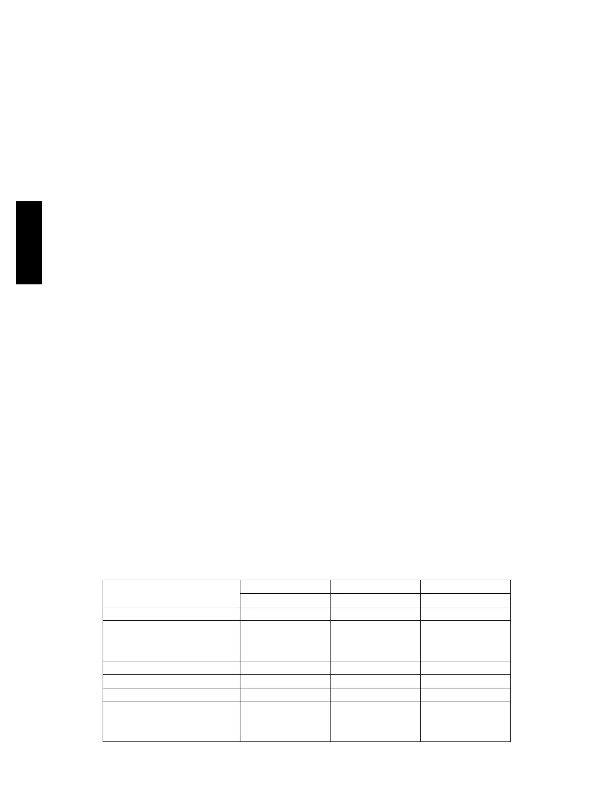
Table 1 – Operating Weights
582J*
UNITS LB (KG) UNITS LB (KG) UNITS LB (KG)
04 05 06
Base Unit 490 (222) 544 (246) 597 (270)
Economizer
Vertical 50 (23) 50 (23) 50 (23)
Horizontal 80 (36) 80 (36) 80 (36)
Perfect Humidity™ System 50 (23) 50 (23) 50 (23)
Cu Fins 25 (11) 43 (20) 56 (25)
Powered Outlet 35 (16) 35 (16) 35 (16)
Curb
14---in/356 mm 115 (52) 115 (52) 115 (52)
24---in/610 mm 197 (89) 197 (89) 197 (89)
582J

 Loading...