36
Table 7 – LEDs
The LEDs on the RTU Open show the status of cert ain functions
If this LED is on... Status is...
Power The RTU Open has power
Rx The RTU Open is receiving data from the network segment
Tx The RTU Open is transmitting data over the network segment
BO# The binary output is active
The Run and Error LEDs indicate control module and network status
If Run LED shows... And Error LED shows... Status is...
2 flashes per second Off Normal
2 flashes per second 2 flashes, alternating with Run LED Five minute auto--- restart delay after system error
2 flashes per second 3flashes,thenoff Control module has just been formatte d
2 flashes per second 4 flashes, then pause Two or more devices on this network have the
same MSTP network address
2 flashes per second On Exec halted after frequent system errors or
control programs halted
5 flashes per second On Exec start ---up aborted, Boot is running
5 flashes per second Off Firmware transfer in progress, Boot is running
7 flashes per second 7 flashes per second, alternating with
Run LED
Ten second recovery period after brownout
14 flashes per second 14 flashes per seco nd,
alternating with Run LED
Brownout
On On Failure. Try the following solutions:
S Turn the RTU Open off, then on.
S Format the RTU Open.
S Download memory to the RTU Open.
S Replace the RTU Open.
NOTE: Refer to the RTU Open multi--pr oto col contr oller
Controls, Start--Up, Operation and Troubleshooting manual
for complete configuration of RTU Open, operating
sequences and troubleshooting information. Contact your
Bryant applications engineer for details on confi guration
and troubleshooting of connec ted networks.
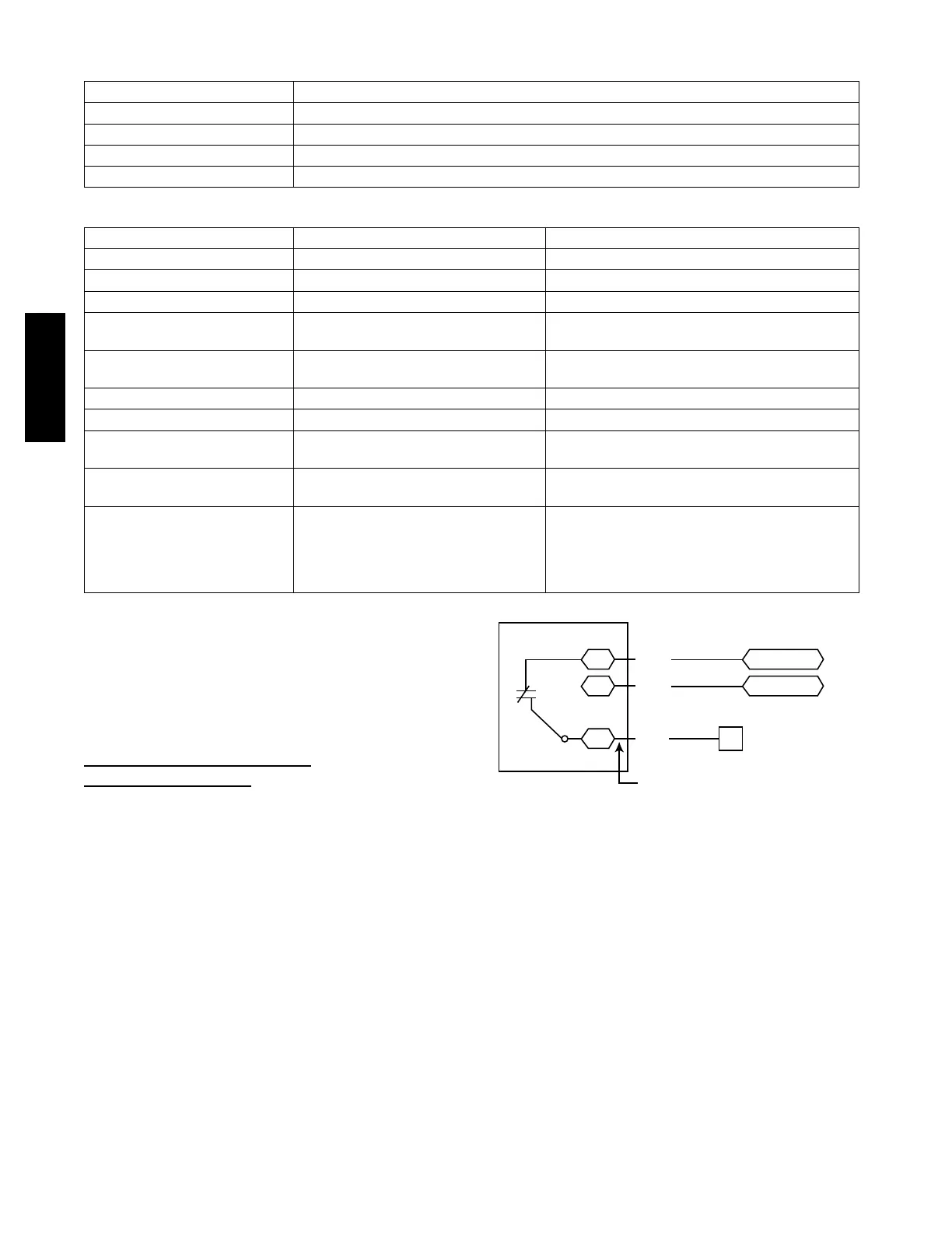
Outdoor Air Enthalpy Control
(PNO
33CSENTHSW)
The enthalpy control (33CSENTHSW) is available as a
field--installed access o ry to be used with the EconoMi$er
R
2
damper system. The outdoor air enthalpy sensor is part of
the enthalp y control. (The s ep arate field--installed acces s o ry
return air enthalpy sensor (33CSENTSEN) is required for
differential enthalpy control. See Fig. 57.)
Locate the enthalpy control in the economizer next to the
Actuato r Motor. Locate two GRA leads in the facto ry
harness and connect the gray lead labeled “ESL” to the
terminal labeled “LOW”. See Fig. 57. Co nn ect the enthalpy
control power input terminals to economizer actuator power
leads RED (connect to 24V) and BLK (connect to GND).
7
CTB ECON
(P’LINK: to J4-2) or
(RTU Open: to J2-6)
LOW
GND
24V
Enthalpy
Switch
GRA
BLK
RED
Factory Wiring Harness
PL6-1 (24-V)
PL6-4 (COM)
C11160
Fig. 57 -- Enthalpy Switch (33CSENTHSW) Connections
The out door enthalpy changeover setpoi nt is set at the
enthalpy controller.
Differential Enthalpy Control —
Differential enthalpy control is provided by sensing and
comparing the outside ai r and return air enthalpy
conditions. Install the outdoor air enthalpy c ontrol as
described above. Add and install a return air enthalpy
sensor.
582J

 Loading...