21
Non--powered type: This type requires the field
installation of a general--purpose 125--volt 15--A circuit
powered from a source elsewhere in the building. Observe
national and local codes when selecting wire size, fuse or
breake r requirements and disconnect switch size and
loca tion. Route 125--v power supply conductors into the
bottom of the utility box containing the duplex receptacle.
Unit--powered type: A unit--mounted transformer i s
fact ory--installe d to stepdown the main power supply
voltage to the unit t o 115--v at the duplex receptacle. This
option also includes a manual switch with fuse, located in
a utility box and mounted on a bracket behind the
convenience outlet; access is through the unit’s control
box access panel. See Fig. 28.
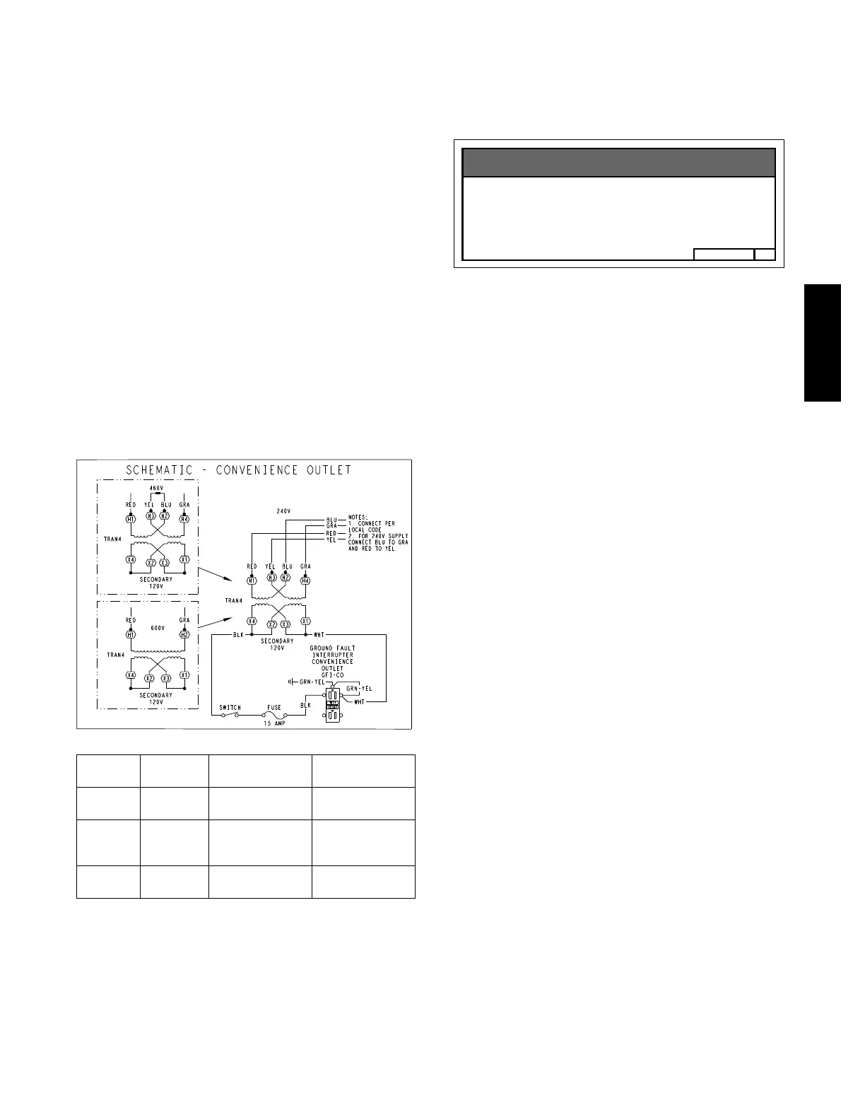
The primary lea ds to the convenience outlet transformer
are not factory--connected. Selection of primary power
source is a customer--option. If local codes permit, the
transformer primary leads can be connected at the
line--side terminals on the unit--mounted non--fused
disconnec t switch; this will provide service power to the
unit when the unit disc onnect switch is open. Other
connec tion methods will result in the conve nience outlet
circuit being de--energized when the unit disconnect
switch is open. See Fig. 30.
C08283
UNIT
VOLTAGE
CONNECT
AS
PRIMARY
CONNECTIONS
TRANSFORMER
TERMINALS
208,
230
240
L1: RED +YEL
L2: BLU + GRA
H1 + H3
H2 + H4
460 480
L1: RED
Splice BLU + YEL
L2: GRA
H1
H2 + H3
H4
575 600
L1: RED
L2: GRA
H1
H2
Fig. 30 -- Powered Convenience Outlet Wiring
Using unit--mounted convenience outlets: Units with
unit--mounted convenience outlet circuits will often
require that two disconnects be opened to de--energize all
power to the unit. Treat all units as electrically energized
until the convenience outlet power is also checked and
de--energization is confirmed. Observe National Electrical
Code Article 210, Branch Circuits, for use of convenience
outlets.
Fuse on power type: The factory fuse is a Bussman
“Fusetron” T--15, non--renewable screw--in (Edison base)
type plug fuse.
B50HJ542739
Maximum Continuous use : 8 Amps 24/7
Convenience Outlet Utilization
NOTICE
C13415
Fig. 31 -- Convenience Outlet Utilization Notice Label
Duty Cycle: the unit--powered convenience outlet has a
duty cycle limitation. The transformer is intended to
provide power on an intermittent basis for service tools,
lamps, etc; it is not intended to provide 15--amps loading
for continuous duty loads (such as e lect ric hea ters for
overnight use). Observe a 50% limit on circuit loading
above 8--amps.
Convenience outlet usage rating:
Continuous usage: 8 amps ma ximum
Test the GFCI receptacle by pressing the TEST button on
the face of the receptacle to trip and open the receptacle.
Check for proper grounding wires and power line phasing
if the GFCI receptacle does not trip as required. Press the
RESET button to clear the tripped condit ion.
Factory--Option Thru--Base Connections (Electrical
Connections)—
This service connection kit consists of a
1
/
2
-- i n N P T g a s
adapter fitting (brass), a
1
/
2
--in electrical bulkhead
connector and a
3
/
4
--in electrical bulkhead connector, all
factory--installed in the embossed (raised) section of the
unit basepa n in the condenser section. The
3
/
4
-- i n
bulkhea d connector enables the l ow--volta ge control wires
to pass through the ba se pan. The
1
/
2
--in electrical
bulkhea d connector allows the high --voltage power wires
to pass through the basepan. See Fig. 16.
Check tightness of connector lock nut s before conne cting
electrical conduits.
Field--supplied and field--installed liquid tight conduit
connec tors and conduit may be attached to the connectors
on the basepan. Pull correctly rated high voltage and low
voltage through appropriate conduits. Connect the power
conduit to the internal disconnect (if unit is so equipped)
or to the external disconnect (through unit side panel). A
hole must be field cut in the main control box bottom on
the left side so the 24--v control connections can be m ade.
Connect the control power conduit to the unit control box
at this hole.
582J

 Loading...