23
Perfect Humidityt Control Connections
Perfect Humidity -- Space RH Controller —
NOTE: Perfect Humidity is a factory installed option
which is only available for units equipped wit h belt--drive
motors. Perfect Humidity is not available for single phase
(--J voltage code) models.
The Perfect Humidity dehumidification system require s a
field--supplied and --installed space relative humidity
control device. This device may be a separate humidistat
control (contact closes on rise in space RH above control
setpoint) or a combination thermostat --humidistat control
devic e such as Bryant’s EDGE
R
Pro Thermidistat with
isolated contact set for dehumidification control.
To connect a field--supplied humidistat:
1. Route the humidista t 2--conductor cable (field--sup-
plied) through the hole provided in the unit corner
post.
2. Feed wires through the raceway built into the corner
post (see Fig. 33) to the 24--v barrier located on the
left side of the control box. The raceway provides the
UL--required clearance between high--voltage and
low--voltage wiring.
3. Use wire nuts to connect humidistat cable to two
PINK leads i n the low–voltage wiring as shown in
Fig. 35.
To connect the Edge Programmable Thermidistat
(T6--PRH01--A):
1. Route the Edge Programmable Thermostat multi--
conductor cable (field--supplied) through the hole
provided in the unit corner post.
2. Feed wires through the raceway build into the corner
post (see Fig. 33) to the 24--v barrier located on the
left side of the control box. The raceway provides the
UL--required clearance between high--voltage and
low--voltage wiring.
3. The E dge Programmable Thermostat has dry contacts
at terminals D1 and D2 for dehumidification
operation (see Fig. 36). The dry contacts must be
wired between CTB terminal R and the PINK lead to
the LTLO switch with field --supplied wire nuts. Refer
to the installation instructions included with the
Bryant Edge Programmable Thermidistat device for
more information.
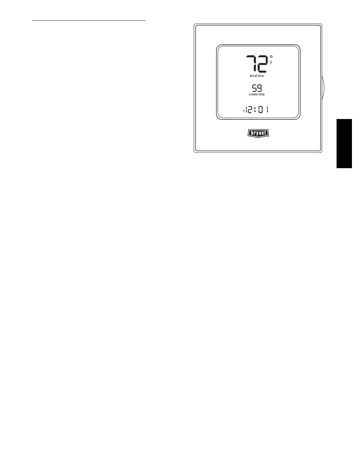
C09502
Fig. 34 -- Edge Programmable Thermostat
582J

 Loading...