29
Table 6 – R TU Open Controller Inputs and Outputs
POINT NAME
BACnet OBJECT
NAME
TYPE OF I/O
CONNECTION PIN
NUMBER(S)
CHANNEL DESIGNATION
DEDICATED INPUTS
Space Temp / Zone Temp zone_temp AI (10K Thermistor) J 2 0 --- 1 & 2 Analog Input 10
Supply Air Temperature sa_temp AI (10K Thermistor) J 2 --- 1 & 2 Analog Input 6
Outside Air Temperature oa_temp AI (10K Thermistor) J 2 --- 3 & 4 Analog Input 7
Space T emperature Offset Pot stpt_adj_offset AI (100K Potent iometer ) J 2 0 --- 3 & 4 Analog Input 11
Safety Chain Feedback safety_status BI (24 VAC) J 1 --- 9 Binary Input 4
Compressor Safety Status
(1)
comp_status BI (24 VAC) J 1 --- 2 Binary Input 3
Fire Shutdown Status firedown_status BI (24 VAC) J 1 --- 1 0 Binary Input 5
Enthalpy Status enthalpy_status BI (24 VAC) J 2 --- 6 & 7 Binary Input 8
Humidistat Input Status humstat_status BI (24 VAC) J 5 --- 7 & 8 Binary Input 9
Zone Temperature n/a n/a J 1 3 --- 1 --- 4 Rnet
CONFIGURABLE INPUTS
(4)
Indoor Air CO2 iaq A I ( 4 --- 2 0 m A )
J 4 --- 2 & 3 o r J 4 --- 5 & 6
Analog Input 2
Outdoor Air CO2 oaq A I ( 4 --- 2 0 m A ) Analog Input 1
Space Relative Humidity space_rh A I ( 4 --- 2 0 m A ) Analog Input 10
Supply Fan Status
(2)
sfan_status BI (24 VAC)
J 5 --- 1 & 2 o r J 5 --- 3 & 4 ,
J 5 --- 5 & 6 o r J 5 --- 7 & 8
(3)
BinaryInput3,5,8,or9,exceptwhereintrinsicinputisused
Filter Status
(2)
filter_status BI (24 VAC) BinaryInput3,5,8,or9,exceptwhereintrinsicinputisused
Door Contact
(2)
door_contact_status BI (24 VAC) BinaryInput3,5,8,or9,exceptwhereintrinsicinputisused
Remote Occupancy input
(2)
occ_contact_status BI (24 VAC) BinaryInput3,5,8,or9,exceptwhereintrinsicinputisused
IGC input
(2)
igcovr_status BI (24 VAC) Binary Input 9. Mandatory input on gas heat units.
OUTPUTS
Economizer Output econ_output AO (4---20mA) J 2 --- 5 Analog Output 1
Supply Fan VFD vfd_output A O ( 2 --- 1 0 V d c ) J 2 2 --- 1 & 2 Analo g Output 2
Supply Fan Relay sfan BO Re lay (24VAC, 1A) J 1 --- 4 Binary Output 1 ( G)
Cool 1 Relay State comp_1 BO Relay (24VAC, 1A) J 1 --- 8 Binary Output 5 (Y1)
Cool 2 Relay State comp_2 BO Relay (24VAC, 1A) J 1 --- 7 Binary Output 4 (Y2)
Cool 3 Relay State comp_3 BO Relay (24VAC, 1A) J 1 1 --- 5 & 6 Binary Output 7 (Y3)
Heat 1 Relay State heat_1 BO R elay (24VAC, 1A) J 1 --- 6 Binary Output 3 (W1)
Heat 2 Relay State heat_2 BO R elay (24VAC, 1A) J 1 --- 5 Binary Output 2 (W2)
Power Exhaust Relay State pexh BO Relay (24VAC, 1A) J11---2&3(N.O.) Binary Output 8 (PE)
Dehumidification Relay dehum BO Relay (24VAC, 1A) J11---7&8(N.O.) Binary Output 6
LEGEND
AI --- A n a l o g I n p u t
AO --- A n a l o g O u t p ut
BI --- B i n a ry I np u t
BO --- Binary Output
(1)
Safety Chain Feedback: 24Vac required at this terminal to provide “Run Enable” status. See Input/Output section for additi onal instructions.
(2)
These inputs are configurable. If installed, they take the place of the default input on the specific channel. See appropriate Input Configuration Section for wiring and setup instructions.
(3)
P a r a l l e l p i n s J 5 --- 1 = J 2 --- 6 , J 5 --- 3 = J 1 --- 1 0 , J 5 --- 5 = J 1 --- 2 a re u s e d f o r f i l e d i n s t a l l a t i o n.
(4)
Refer to the input configuration and accessory sections of the RTU Open Multi ---Protocol Controller Controls, Start ---Up, Operation and Troubleshooting manual for more detail.
The RTU Open controller requires the use of a Bryant
space sensor. A standard thermostat cannot be used with
the RTU Open system.
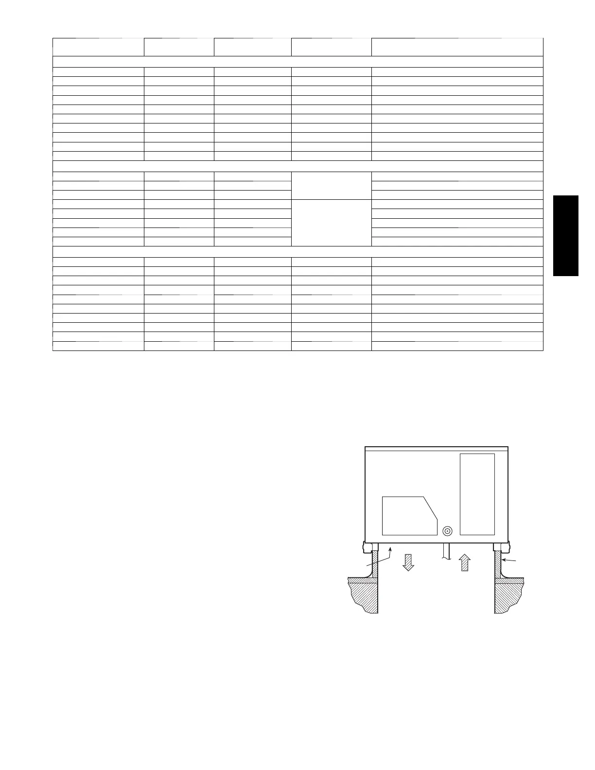
Supply Air Temperature (SAT) Sensor —
On FIOP--equipped 582J unit, the unit is supplied with a
supply--air temperature (SAT) sensor (33ZCSENSAT).
This sensor is a tubular probe type, approx 6--inches (152
mm) in length. It is a nominal 10--k ohm thermistor.
The SAT is factory--wired. The SAT probe is wire--tied to
the supply--air opening (on t he horizontal opening end) in
its shipping position. Remove the sensor for installat ion.
Re--position the sensor in the flange of the supply--air
opening or in the supply air duct (as required by local
codes). Drill or punch a
1
/
2
--in. hole in the flange or duct.
Use two field--supplied, self--drilling screws to secure the
sensor probe in a horizontal orientation. See Fig. 41.
Outdoor Air Temperature (OAT) Sensor —
The OAT is factory--m ounted in the EconoMi$er
R
2(FIOP
or accessory). It is a nominal 10k ohm thermistor attached
to an eyelet mounting ring.
SUPPLY AIR
RETURN AIR
SUPPLY AIR
TEMPERATURE
SENSOR
ROOF
CURB
C08200
Fig. 41 -- Typical Mounting Location for Supply Air
Temperature (SAT) Sensor on Small Rooftop Units
582J

 Loading...