926SB: Installation, Start-up, Operating, Service and Maintenance Instructions
Manufacturer reserves the right to change, at any time, specifications and designs without notice and without obligations.
25
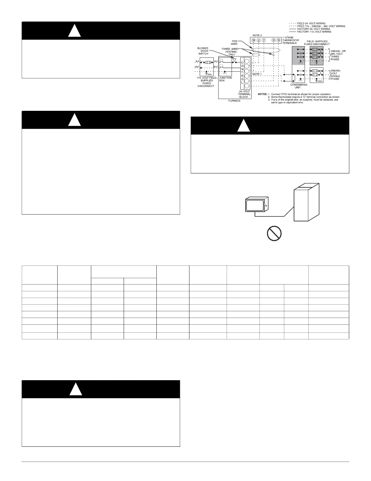
See Fig. 33 for field wiring diagram showing typical field 115-V wiring.
Check all factory and field electrical connections for tightness.
Field-supplied wiring shall conform with the limitations of 63_F (33_C)
rise.
A200307
Fig. 33 – Typical Field Wiring Diagram
A190279
Fig. 34 – Field-Supplied External Electrical Box on Furnace Casing
Table 12 – Electrical Data
115-V Wiring
Furnace must have a 115-V power supply properly connected and
grounded.
NOTE: Proper polarity must be maintained for 115-V wiring. If polarity
is incorrect, control LED status indicator light will flash rapidly and
Status code (10.1) is displayed. The furnace will NOT operate.
Verify that the voltage, frequency, and phase correspond to that specified
on unit rating plate. Also, check to be sure that service provided by
utility is sufficient to handle load imposed by this equipment. Refer to
rating plate or Table 12 for equipment electrical specifications.
WARNING
!
ELECTRICAL SHOCK HAZARD
Failure to follow this warning could result in personal injury or death.
Blower door switch opens 115-V power to control. No component
operation can occur. Do not bypass or close switch with blower door
removed.
WARNING
!
ELECTRICAL SHOCK AND FIRE HAZARD
Failure to follow this warning could result in personal injury, death, or
property damage.
The cabinet MUST have an uninterrupted or unbroken ground
according to current edition of NEC NFPA 70 or local codes to
minimize personal injury if an electrical fault should occur. In Canada,
refer to the current edition of Canadian Electrical Code CSA C22.1.
This may consist of electrical wire, conduit approved for electrical
ground or a listed, grounded power cord (where permitted by local
code) when installed in accordance with existing electrical codes. Refer
to the power cord manufacturer’s ratings for proper wire gauge. Do not
use gas piping as an electrical ground.
WARNING
!
FIRE HAZARD
Failure to follow this warning could result in personal injury, death, or
property damage.
Do not connect aluminum wire between disconnect switch and furnace.
Use only copper wire. See Fig. 34.
COPPER
WIRE ONLY
ELECTRIC
DISCONNECT
SWITCH
ALUMINUM
WIRE
FURNACE
SIZE
VOLTS-
HERTZ-
PHASE
OPERATING VOLTAGE
RANGE
*
*. Permissible limits of the voltage range at which the unit operates satisfactorily.
MAXIMUM
UNIT
AMPS
UNIT
AMPACITY
†
†. Unit ampacity = 125 percent of largest operating component’s full load amps plus 100 percent of all other potential operating components’ (EAC, humidifier,
etc.) full load amps.
MINIMUM
WIRE SIZE
AWG
MAXIMUM
WIRE LENGTH
FT (M)
‡
‡. Length shown is as measured one way along wire path between furnace and service panel for maximum 2 percent voltage drop.
MAX FUSE OR
CKT BKR
AMPS
**
**. Time-delay type is recommended.
Maximum Minimum
30040V14 115-60-1 127 104 7.0 9.7 14 38 11.7 15
36040V17 115-60-1 127 104 7.4 10.2 14 36 11.1 15
36060V14 115-60-1 127 104 7.1 9.8 14 38 11.5 15
42060V17 115-60-1 127 104 10.1 13.6 14 27 8.3 15
48080V17 115-60-1 127 104 10.0 13.4 14 27 8.4 15
60080V21 115-60-1 127 104 13.1 17.3 12 33 10.1 20
60100V21 115-60-1 127 104 13.2/11.3
††
††. Low Amp Kit (KGAPC0101ECM) allows select furnaces to be installed with a 15 Amp breaker and 14 AWG wire within the listed wire length. Affected data shown as Default
Value/Value with Lower Amp Kit.
17.4/15.0
††
12/14
††
33/24
††
10/7
††
20/15
††
66120V24 115-60-1 127 104 12.6 16.7 12 34 10.5 20
CAUTION
!
FURNACE MAY NOT OPERATE HAZARD
Failure to follow this caution may result in intermittent furnace
operation.
Furnace control must be grounded for proper operation or else control
will lock out. Control must remain grounded through green/yellow wire
routed to gas valve and manifold bracket screw.