926SB: Installation, Start-up, Operating, Service and Maintenance Instructions
Manufacturer reserves the right to change, at any time, specifications and designs without notice and without obligations.
64
f. After servicing the blower, reverse steps a through e, resealing
combustion air pipe per installation instructions.
g. Tighten all clamps 15 lb -in.
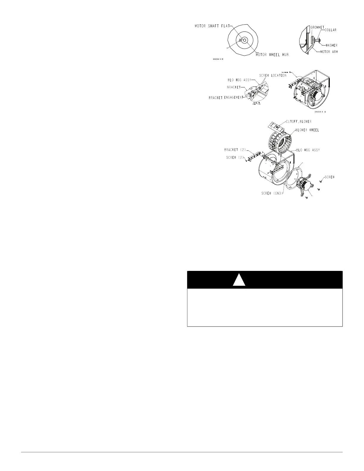
See Fig. 66 For Steps 5 through 14.
5. Remove screws securing blower assembly to blower shelf and slide
blower assembly out of furnace. Detach ground wire and
disconnect blower motor harness plugs from blower motor.
NOTE: Blower wheel is fragile. Use care.
6. Clean blower wheel and motor by using a vacuum with soft brush
attachment. Be careful not to disturb balance weights (clips) on
blower wheel vanes. Do not bend wheel or blades as balance will be
affected.
7. If greasy residue is present on blower wheel, remove wheel from
the blower housing and wash it with an appropriate degreaser. To
remove wheel:
NOTE: The DIBC composite wheel used in some models should be
cleaned with mild soapy water only. Allow wheel to dry prior to
reassembly.
a. Mark blower wheel location on shaft before disassembly to
ensure proper reassembly.
b. Loosen setscrew holding blower wheel on motor shaft.
NOTE: Mark blower mounting arms and blower housing so each arm is
positioned at the same hole location during reassembly.
c. Mark blower wheel orientation and cutoff plate location to
ensure proper reassembly.
d. Remove screws securing cutoff plate and remove cutoff plate
from housing.
e. Remove bolts holding motor mounts to blower housing and slide
motor and mounts out of housing.
f. Remove blower wheel from housing.
g. Clean wheel per instructions on degreaser cleaner. Do not get
degreaser in motor.
8. Reassemble motor and blower wheel by reversing items 7b through
7f. Ensure wheel is positioned for proper rotation.
9. Torque motor mounting bolts to 40 +/- 10 lb-in. when reassembling.
10. Torque blower wheel set screw to 160 +/- 20 lb-in. when
reassembling.
11. Verify that blower wheel is centered in blower housing and set
screw contacts the flat portion of the motor shaft. Loosen set screw
on blower wheel and reposition if necessary.
A190094B
Fig. 66 – Blower Assembly
12. Spin the blower wheel by hand to verify that the wheel does not rub
on the housing.
13. Reinstall blower assembly in furnace.
14. Reinstall 2 screws securing blower assembly to blower deck.
15. Reconnect blower leads to furnace control. Refer to furnace wiring
diagram, and connect thermostat leads if previously disconnected.
NOTE: Be sure to attach ground wire and reconnect blower harness
plugs to blower motor.
16. Downflow or horizontal furnaces with vent pipe through furnace
only:
a. Install and connect short piece of vent pipe inside furnace to
existing vent.
b. Connect vent connector to vent elbow.
17. Turn on electrical supply. Manually close blower door switch.
Check for proper rotation and speed changes between heating and
cooling by jumpering R to G and R to Y/Y2 on furnace control
thermostat terminals. If outdoor temperature is below 70_F, turn off
circuit breaker to outdoor unit before running furnace in the cooling
cycle. Turn outdoor circuit breaker on after completing cooling
cycle. See Fig. 38.
NOTE: If R-W thermostat terminals are jumpered at the time blower
door switch is closed, blower will run for 90 sec before beginning a
heating cycle.
a. Perform component self-test as shown at the bottom of the
SERVICE label, located on the blower door.
WARNING
!
ELECTRICAL OPERATION HAZARD
Failure to follow this warning could result in personal injury or death.
Blower door switch opens 115-V power to control. No component
operation can occur unless switch is closed. Caution must be taken
when manually closing this switch for service purposes.
TORQUE THE BLOWER
WHEEL SET SCREW
160 LB-IN +/- 20 LB-IN.
BLOWER INLET
ORIFICE
BLOWER MOTOR