22
A07219
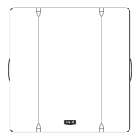
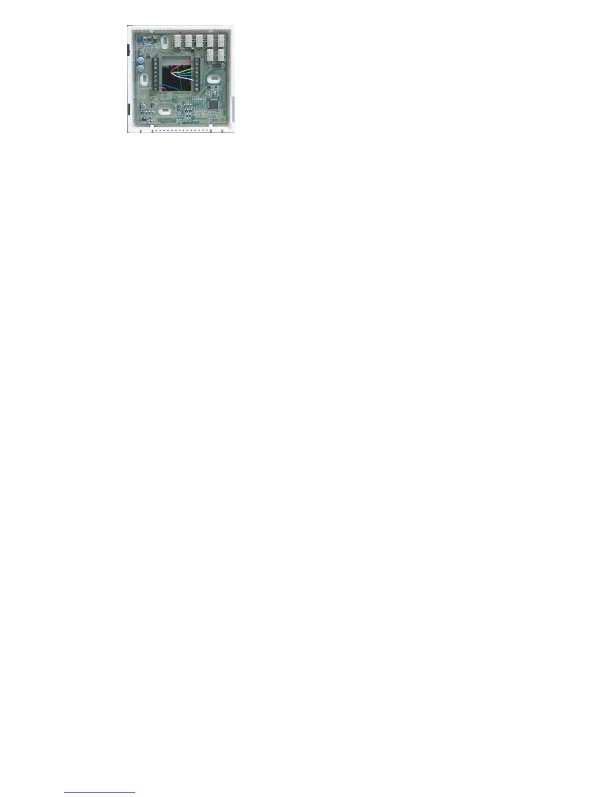
Fig. 14 -- Equipment Control Module
5. Match and connect equipment wires to proper terminals of each connector
block.
6. Push any excess wire into wall and against Equipment Control Module.
Seal hole in wall to prevent air leaks. Leaks can affect operation and cause
incorrect temperature and/or humidity measurement.
7. Attach 2--wire pigtail to Equipment Control Module terminal block (ter-
minals V+ and Vg). Attach 2--wire pigtail to the back of the Display
Module via 2 pin, keyed connector.
8. Reattach Display Module body to Equipment Control Module by first
setting on at top and then push bottom corners to snap into place. See Fig.
15.
 Loading...