Quick Reference Guide QRG
DIL switch
S4.7 S4.8
Seelction of the used
servo-center component
OFF OFF Position feed back EMS 17, EMS 21, EMS 22
(potentiometer)
ON OFF
OMG 8
OFF ON No servo-center component
(center position cannot be selected)
ON ON
OMG 4
DIL switch S5 matches the control parameters to the sensors that
are being used.
The system recognizes the CLS Pro 600 sensor automatically.
Therefore don’t carry out here any settings.
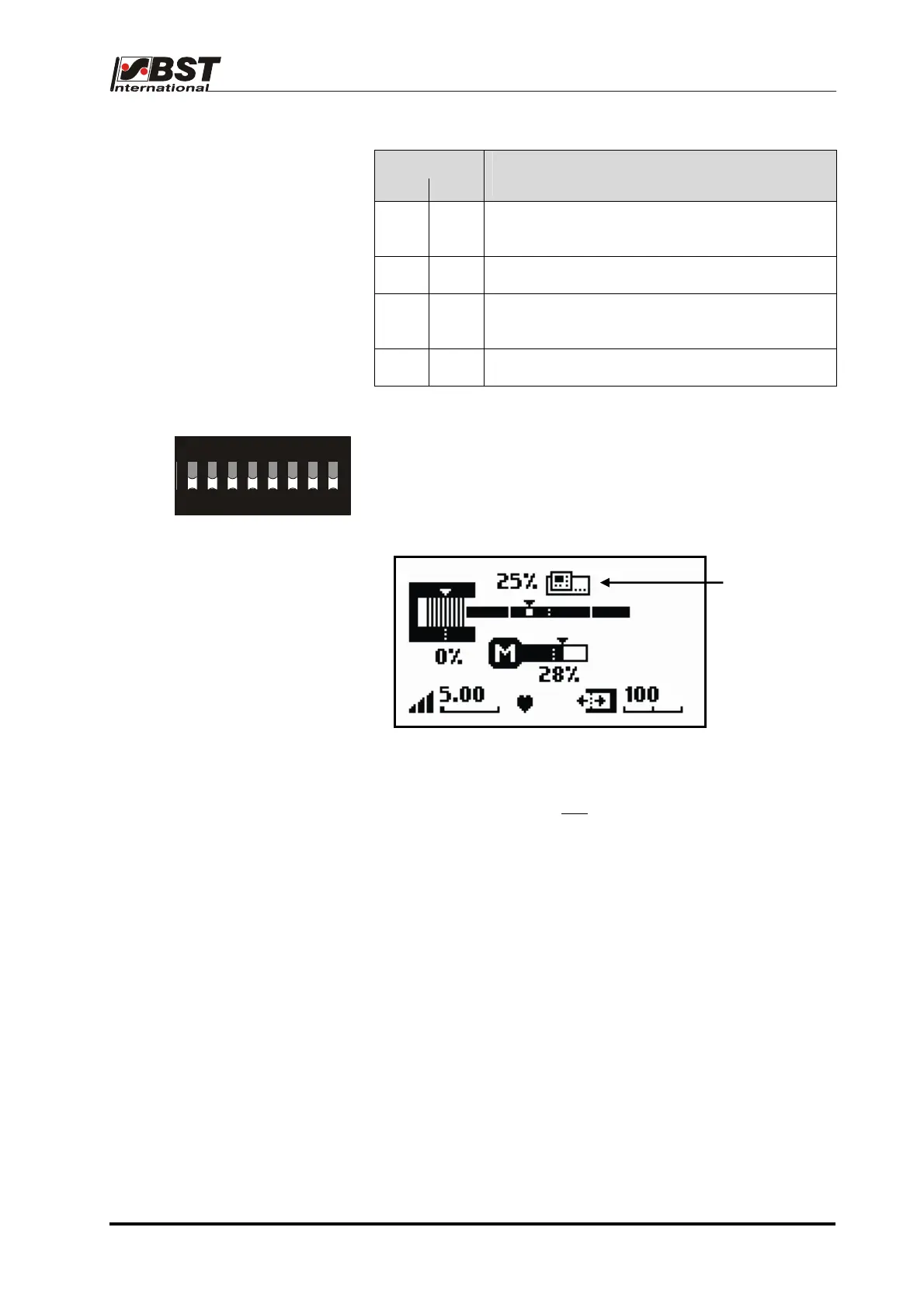
The operating display of the ekr 500 Plus is displayed as follows:
ON DIP
CLS Pro 600
recognized
12345678
DIL-Schalter S5
The edge sensors are displayed only if they are really connected
resp. the DIL switches are set accordingly.
Within the above example, one
edge sensor (sensor 1) is
connected.
Setting is carried out according to the manual ekr 500 / ekr 500
Plus.
Quick Reference Guide EDV no.: MD.341.01.01
ekr 500 Plus with CLS Pro 600 Issue Date: 31.03.2009 Page: 4/18

 Loading...
