2
Functional Description
12/67 ekr 500 digital Unit Touch – CANopen User Gateway
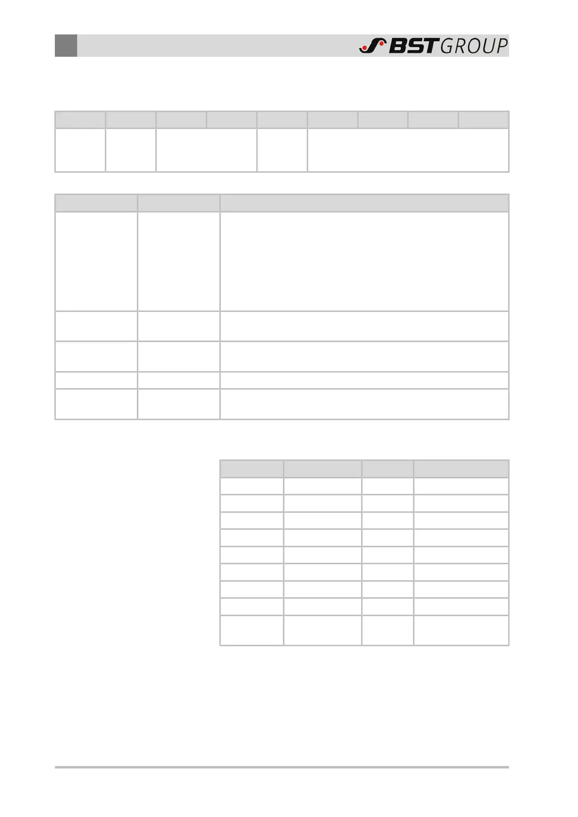
2.3.1.1 Structure of a Service Data Object
The structure of a Service Data Object is as follows:
Identifier Byte 1 Byte 2 Byte 3 Byte 4 Byte 5 Byte 6 Byte 7 Byte 8
600h +
node
number
Control
byte
Index Sub-index Data field
It consists of the following components:
Component Content Function
Identifier
600h +
node number of
the controller
The identifier determines the intended recipient of the message
in the bus system.
The node number (device address) is set using the rotary switch
S1 on the processor board of the controller.
The procedure is described in the installation and commissioning
manual of the ekr 500 digital Unit Touch controller (document
number MD.497).
Byte1 Control byte
The control byte determines whether the Service Data Object has
write or read access to the entry in the object dictionary.
Byte2…Byte3 Index
The index is the main entry in the object dictionary dividing the
parameters into groups.
Byte4 Sub-index The sub-index divides the parameters within a group of parameters.
Byte5…Byte8 Data field
These components are used for the exchange of the actual user
data.
2.3.1.2 Data Types Used
Data Type Data Width Sign Value Range
Unsigned8 8 Bit = 1 Byte Unsigned 0…255
Unsigned16 16 Bit = 2 Byte Unsigned 0…65535
Unsigned24 24 Bit = 3 Byte Unsigned 0…2
24
Unsigned32 32 Bit = 4 Byte Unsigned 0…2
32
Signed8 8 Bit = 1 Byte Signed -127…+126
Signed16 16 Bit = 2 Byte Signed -32768 … 32767
Signed24 24 Bit = 3 Byte Signed -(2
24
)…(2
24
-1)
Signed32 32 Bit = 4 Byte Signed -(2
31
)…(2
31
-1)
Float 32 Bit Signed
Floating point value
with 32 Bit
 Loading...


