P
Pamela WongSep 2, 2025
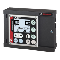
Why is my BST ekr 500 locked?
- AAmy McbrideSep 2, 2025
If the BST Controller isn't responding and the display shows a key symbol, the keyboard interlock is active. To deactivate it, remove the jumper from terminal 81-82.

Why is my BST ekr 500 locked?
If the BST Controller isn't responding and the display shows a key symbol, the keyboard interlock is active. To deactivate it, remove the jumper from terminal 81-82.
What does it mean when the BST Controller display shows a warning symbol and the actuator doesn't move?
If the BST Controller's actuator isn't moving and the display shows a warning symbol, the controller interlock is likely active. To resolve this, deactivate the controller interlock by inserting a jumper on terminal 54-55.
Why does BST Controller actuator stay at the end position in center positioning mode?
If the BST Controller's actuator moves to an end position and remains there in center positioning mode, the actuator guiding direction might be set up wrongly or the servo-center transducer being used has been incorrectly installed. Reverse the guiding direction of the actuator and check the mounting position of the servo-center transducer.
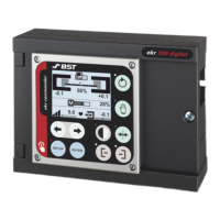
What does the warning symbol on my BST ekr 500 Controller mean?
If the BST Controller's display shows a warning symbol, it could be that the controller supply voltage is outside the permissible range. Check the power supply and the mains wiring.
Why does my BST ekr 500 actuator stay at the end position in automatic mode?
If, in automatic mode, the BST Controller's actuator moves to an end position and stays there, it might be because a material setup wasn't run after changing the material, or the actuator guiding direction is set up wrongly. Carry out a material setup and reverse the guiding direction of the actuator.
Why is my BST ekr 500 Controller not responding?
If the BST Controller isn't responding, a remote control might be connected, locking the control panel keys, or the device address of the controller/control panel might be set incorrectly. Deactivate the remote control and check the setting of the rotary switch S1 in the controller and the control panel.
What to do if BST ekr 500 Controller actuator does not move?
If the BST Controller's actuator isn't moving, it could be due to a wrong actuator selection during start-up or the gain being set too low. Check the adjustment of DIL switch S4 in the controller and optimize the gain.
How to stop BST ekr 500 Controller actuator from trembling?
If the actuator or guiding device of your BST Controller is trembling, it could be due to guiding system overdrive. Try optimizing the gain and carry out a material setup to resolve this.
| Brand | BST |
|---|---|
| Model | ekr 500 |
| Category | Controller |
| Language | English |
Explains warning signs, key usage, and LED status indications for manual comprehension.
Covers general information and essential adherence to operating instructions for the controller.
Details the system structure, functional principle, and connectable components of the web guiding system.
Lists essential safety regulations, ESD protection, emissions, and RoHS conformity.
Details ambient conditions, protection class, power supply, and I/O for the controller unit.
Outlines ambient conditions, protection class, power, display, and dimensions for the control panel.
Provides technical details for various infrared, ultrasonic sensors, and electric-motor-driven actuators.
Instructions for shipping and storing the web guiding system components safely and correctly.
Guidelines for selecting an appropriate location for mounting the controller and panel.
Steps for mounting the controller and control panel, including dimensions and options.
Guidelines for fitting cable connections, EMC wiring, and terminal/plug assignments.
How to configure the controller using DIL switches for various functions and component selections.
Explains the meaning of various service LEDs on the processor board for status monitoring.
Steps for starting up the actuator, checking motor rotation, guiding direction, and material setup.
Procedure for optimizing controller gain and setting the web set point for stable guiding.
Explains the control panel display, special displays, and operating mode selection.
Detailed steps for automatic and manual material setup for web edge and center-line guiding.
Enables remote control via external switches or PLC signals, with truth table.
How to set device addresses for the controller and control panel using rotary switches.
Instructions for configuring internal terminating resistors for controller and panel.
Lists common issues, their possible causes, and solutions with references to other sections.
Safety precautions and general procedures for maintaining the controller and panel.
Maintenance requirements for the controller, control panel, sensors, and actuators.
Procedures for scrapping the guiding system in compliance with legal requirements.
Diagram of the processor board, terminal strips, and power supply connection.
Wiring diagrams and DIL switch settings for infrared and ultrasonic sensors.
Wiring diagrams and DIL switch settings for various actuators.
Wiring and DIL switch settings for servo-center transducers OMG 8 and OMG 4.
Wiring for remote control, enable controller, relay contact, and EFE options.