Instruction Manual
14
06/23
performance to suit your application. Further detail is provided below and in the on-line user manual.
The button at the top right of the screen will provide access to the following settings via the on-screen menus:
Test Voltage
The instrument will generate a voltage between 0.9kV and 40kV. In general, the test voltage should be
set to a level that will ensure the detection of flaws through the thickness of the material under test, but
not so high as to risk causing damage to the material itself. Various standards are available, and
Buckleys can provide guidance. However, in all cases, it is recommended to first test on sacrificial
samples to confirm the theoretical approach.
Alarm Threshold
The instrument sensitivity may be set from 10µA (most sensitive) up to 450µA, and to
Spark Only
mode
(least sensitive). The preferred approach is to set the alarm threshold at the lowest (and most sensitive)
level that avoids false alarms, with some allowance for variability. The actual setting will be critically
dependent on the material being tested and the environmental conditions under which the tests are
conducted. Again, sacrificial samples are recommended to validate the setting, particularly in process
control applications.
Alarm Mode
There are four settings for the alarm mode which are located in the
Alarm Menu
. These affect the way
the counter increments when a flaw is detected.
When an alarm state is generated, the screen of the unit will change from Blue (HV Active) to Red
(Alarm), and the internal buzzer will sound.
The internal relay will change state whilst the alarm is active and will return to the rest state when the
alarm state concludes.
Depending on the operating conditions, and particularly in process applications, the time during which
a flaw may be within the area covered by the test electrode might be extremely brief, potentially only
a few microseconds. However, the alarm indication must persist long enough for the user to observe it,
typically at least a few seconds. If the relays are used, it must also be maintained for a sufficient period
for the relay to physically change state. Similarly, there must be a finite time period following an alarm
state to permit the relay to return to the rest state.
In order to control the way in which alarms are managed, the
Alarm Mode
may be selected from these options:
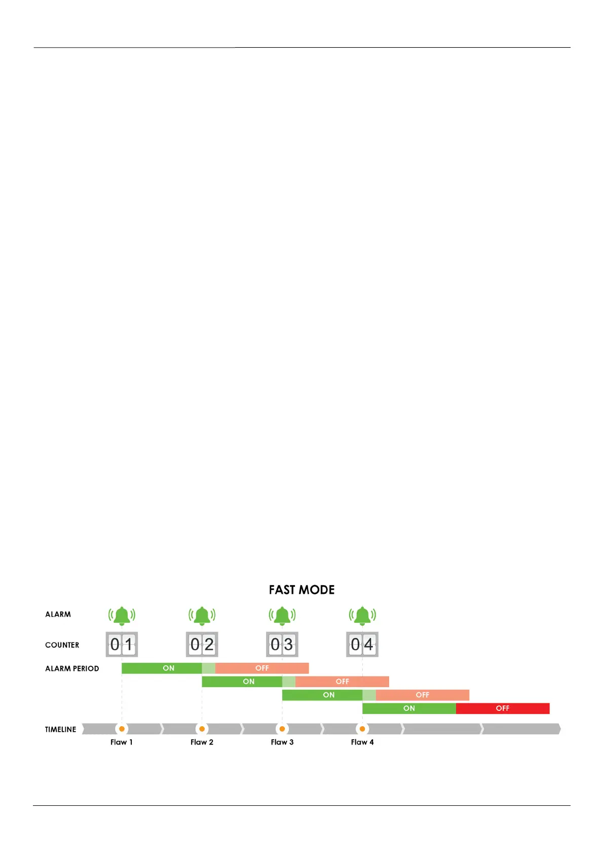
FAST MODE
In
FAST
mode, the counter will increment whenever a flaw is detected, even if an alarm is already
active. There is an effective hardware limitation of approximately 10 microseconds during which a
second flaw will not be registered.
Fig 8 – FAST MODE