Initial start-up 2
Wall-mounted condensing gas boiler Buderus 800 - Subject to modifications resulting from technical improvements!
31
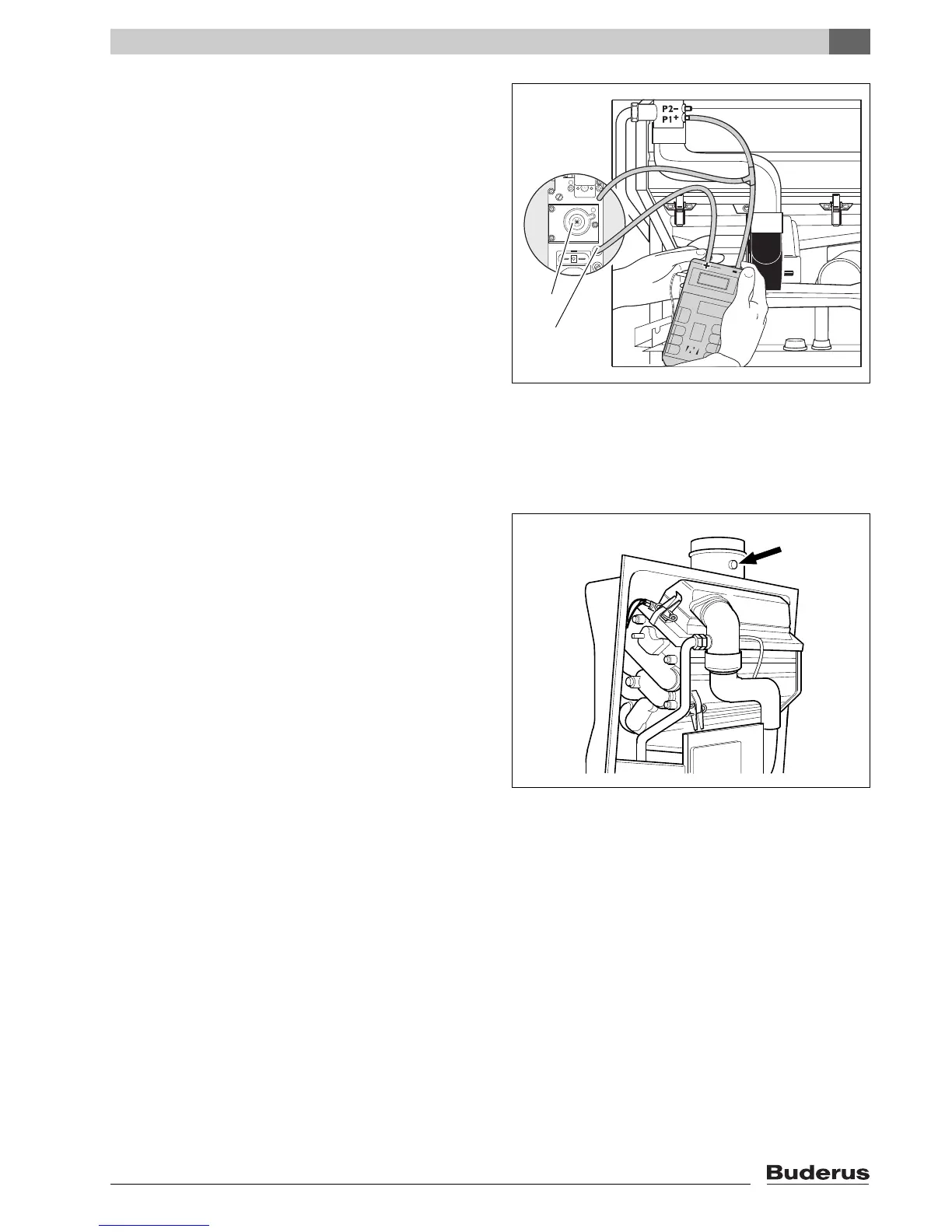
Move the hot water temperature controller to "1".
Read the differential pressure.
The differential pressure (p
Gas
- p
Air
) must be -5 Pa
(±5 Pa) (display on the meter: -10 to 0 Pa).
In case of gas/air ratio deviations, adjust by using the
setscrew (fig. 38, item 3 or fig. 39, item 2).
Set mains switch and chimney sweeper switch to "0".
Remove the measuring equipment, tighten up the
screw in the burner pressure measuring nipple, put
the hose back on P1.
Set the hot water temperature controller back to the
original value.
Move the mains switch to "I".
Adjustment according to the CO
2
content (natural
gas):
The mains switch must be set to "I" and the chimney
sweeper switch to "1".
Press the service button (fig. 37) until "Y" is shown on
the display.
Full load
Move the hot water temperature controller to "10".
Measure and record the CO
2
content on the flue gas
measuring point (fig. 40).
Partial load
Set the hot water temperature controller to "1".
Measure and record the CO
2
content.
The CO
2
content under partial load must be 0.7 %
lower than the one under full load.
If the measured value is too high or too low, use the
setscrew of the gas burner unit (fig. 38, item 3 or
fig. 39, item 2) to set the gas/air ratio under partial
load.
Set the hot water temperature controller to the origi-
nal value.
Set the chimney sweeper switch to "0".
2.2.5 Checking for leaks in operational condition
Check with the burner running, all joints across the
entire gas route of the burner using a foaming agent.
The agent must be certified as a gas leak test agent.
Do not apply the agent to electrical connection ca-
bles.
fig. 39 Checking and adjusting the gas/air ratio (SIT gas
unit)