4
Dimensions and connections
Logamax plus GB162- 80/100 kW - Subject to modifications resulting from technical improvements!
11
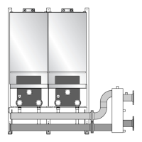
4.2 With pump group
Fig. 3 Dimensions and connections with pump group
A(LA) =Flue gas connection; inside diameter 4" (100 mm)
B(AA) =Air intake with pompadour; inside diameter 4"
(100 mm)
C(WB) =Wall Bracket (not shown)
D(VK) =Supply; G1½" union nut with female thread
E(GAS) =Gas connection to boiler; Rp1" female thread
F(RK) =Return; G1½" union nut with female thread
G(AKO) =Condensate outlet; Ø 32 mm (1¼")O/D
H(PF) =Pump group supply; G1½" male thread, flat seal
I = Gas connection to pump group; 1" NPT female
thread
J(PR) =Pump group return; G1½" malethread, flat seal
The required permanent clearances (closet) are:
in front: 1" (25 mm)
right side: 0
left side: 0
above: 6" (152 mm)
The position selected for installation MUST allow
adequate space for servicing in front of the boiler of at
least 16.5" + 20.5" = 37" (940 mm).
Maintain an installation clearance from combustible
construction from hot water piping of at least 1" (25 mm)
G
C
DFE
4.1” (103.5 mm)
38.58” (980 mm)
5.3” (135 mm)
1.4” (35 mm)
5.4” (138 mm)
6.4” (162 mm)
1.54” (39 mm)
5.1” (130 mm)
5.5” (140 mm)
5.1” (130 mm)
AB
0 020.5” (520 mm)
39.5” (1003 mm)
40,55” (1030 mm)
51.6” (1310 mm)
16” (406 mm)
G
D/F
E
A/B
6” (152 mm)
18.3” (465 mm) 0.25” (6 mm)
H/J
G
HI
J
1.2” (30 mm)
50.4” (1280 mm)
24.8” (630 mm)
16.5" (420 mm)
20.5" (520 mm)
6720645916-03.1TD
 Loading...