7
Electrical connections
Logamax plus GB162- 80/100 kW - Subject to modifications resulting from technical improvements!
30
• Click the function module(s) into position in the wall
bracket (fig. 39).
• Remove the drawer.
Fig. 40
Removing the covers
• Remove the covers of both free connectors on the
function module connection cables (fig. 40).
• Slide the drawer back into the boiler.
Fig. 41 Interconnecting modules
• Connect the free 120 VAC mains cable (fig. 40)to the
module (fig. 41, [1). If more modules are used, the
120 VAC supply for the second module can be taken
from the first module using the cable enclosed with the
module.
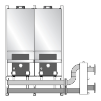
Fig. 42 Connecting several modules
• Connect the free connector of the EMS bus
connecting cable (fig. 41)to the first module (fig. 42).
• If more modules are used, the EMS bus connection for
the second module may be branched off from the first
module using the cable enclosed with the module
(fig. 41 & fig. 42).
7.2.2 Installing function modules outside the
boiler
Fig. 43 EMS bus polarity
• Install the module on the wall according to the
installation instructions of the module.
6 720 646157-40.1N
6 720 646157-4
1
2
NOTICE
B The module may have the letters RC or
EMS above the connection (fig. 42, [1]).
NOTICE
Pay attention to the polarity when using an
EMS bus connection cable
B Connect the wire from terminal 1 to
terminal 1 and from terminal 2 to
terminal 2 (fig. 41and fig. 42).
6 720 646157-42.1
1
6 720 646157-43.1N
 Loading...