6
Installation
Logamax plus GB162- 80/100 kW - Subject to modifications resulting from technical improvements!
25
Do not exceed the total equivalent venting length of 100
feet (30,480 mm) maximum requirement each for the
intake and exhaust piping.
Æ table 8 for the Friction Loss Equivalent in piping and
fittings.
Example:
When you end up using 3 x 45° -elbows and the concen-
tric roof terminal, then the total venting length may not
exceed 68 ft. (20.72 m).
3×45°-elbow = 3 x 4ft. (1.22m) = 12ft. (3.66m)
concentric roof terminal 4"/6" = 20 ft. (6.10 m)
Total friction loss equivalent = 32 ft. (9.76 m)
Total venting length for this example is:
GB162-80 kW/100kW = 100 ft. (30.48 m) - 32 ft. (9.76
m) = 68 ft. (20.72 m) each for the intake and exhaust
piping.
At the time of removal of an existing boiler, the following
steps shall be followed with each appliance remaining
connected to the common venting system placed in
operation, while the other appliances remaining
connected to the common venting system are not in
operation:
a) Seal any unused openings in the common venting
system.
b) Visually inspect the venting system for proper size and
horizontal pitch and determine there is no restriction,
leakage, corrosion and other deficiencies which could
cause unsafe condition.
c) Place in operation the appliance being inspected.
Follow the lighting instructions. Adjust thermostat so
appliance will operate continuously.
d) Test for spillage at the draft hood relief opening after 5
minutes of burner operation. Use the flame of a match or
candle, or smoke from a cigarette, cigar or pipe.
e) Any improper operation of the common venting system
should be corrected so the installation conforms with the
National Fuel Gas Code, ANSI Z223.1/NFPA 54 and/or
CAN/CSA B149.1, Natural Gas and Propane Installation
Code.
When resizing any portion of the common venting system,
the common venting system should be resized to
approach the minimum size as determined using the
appropriate tables in Part 11 of the National Fuel Gas
Code, ANSI Z223.1/NFPA 54 and/or CAN/CSA B149.1,
Natural Gas and Propane Installation Code.
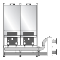
6.9 Multiple boiler vent terminal
clearance
Vertical terminations:
The combustion air inlet pipe must terminate in a down-
ward position using 2 × 90° elbows. The combustion air
inlet pipe shall terminate at least 3 ft (914 mm). horizon-
tally from the center line of the exhaust vent, this is to
prevent cross contamination of flue gases into the
combustion air stream.
Terminate all exhaust vents at the same height and all
combustion air inlets at the same height, while maintaining
the minimum 36" (914 mm) height clearance from the
exhaust to the down turned 90° elbow and combustion air
inlet.
Exhaust vent termination edge shall be at least
24" (610 mm) from the edge of the air inlet pipe of an
adjacent heater. Exhaust vent terminations shall be placed
at a minimum of 12" (305 mm) center to center.
(Æ fig. 30 & fig. 31) Air intake terminations may be
placed adjacent to each other. The combustion air inlet is
part of the direct vent system and not classified as a
forced air inlet.
NOTICE
B Appliance input rates are based on
minimum vent length operation. Longer
vent lengths (up to maximum) will
reduce the input proportionally.
Fittings or Piping
Equivalent
feet m
45° elbow 4 1.22
90° elbow 7 2.13
plastic pipe per foot 1 0.30
parrallel vent kit 2 0.61
concentric roof terminal
4"/6" (100/150 mm)
20 6.10
Tab. 8 Friction Loss Equivalent in piping and fittings
NOTICE
B The minimum covering wall thickness is
1" (25.4 mm). The maximum covering
wall thickness is 16" (406 mm).
B For direct venting properly reassemble
and reseal the vent and air-intake
systems.
CAUTION:
B Vent connectors serving appliances
vented by natural draft shall not be
connected into any portion of
mechanical draft systems operating
under positive pressure.
 Loading...