7
Boiler block assembly
Logano G515 – 6 720 647 208 (2014/09) 17
Use a size 2.2 or 2.3 boiler assembly tool ( Fig. 4, Fig. 5 and Fig. 20
[1 and 2]).
▶ Push pressure flanges ( Fig. 20, [3]) with clamping nuts onto the
tie rods ( Fig. 4, page 11 and Fig. 5, [4]).
▶ Push a tie rod through the upper and lower hubs on the boiler.
▶ Push mating flanges onto the tie rods and secure each with wedge
(dowel pin for assembly tool 2.2).
▶ Hold the tie rod in the center of the boiler hubs and slightly draw
together the assembly tools using the clamping nut.
▶ Place ratchet wrench onto clamping nuts and compress boiler
sections by tightening evenly.
Fig. 20 Using the boiler assembly tool
▶ Release and remove the boiler assembly tool.
▶ Check nipples are seated correctly.
Fig. 21 shows the rear section with intermediate section fitted. The
preparations for fitting the next intermediate section have also been
made.
The boiler section has been equipped with foot wedges for ease of
installation ( Fig. 21, [1]).
The boiler section foot wedges are also used later for final leveling of the
boiler block.
Fig. 21 Using the boiler section foot wedges
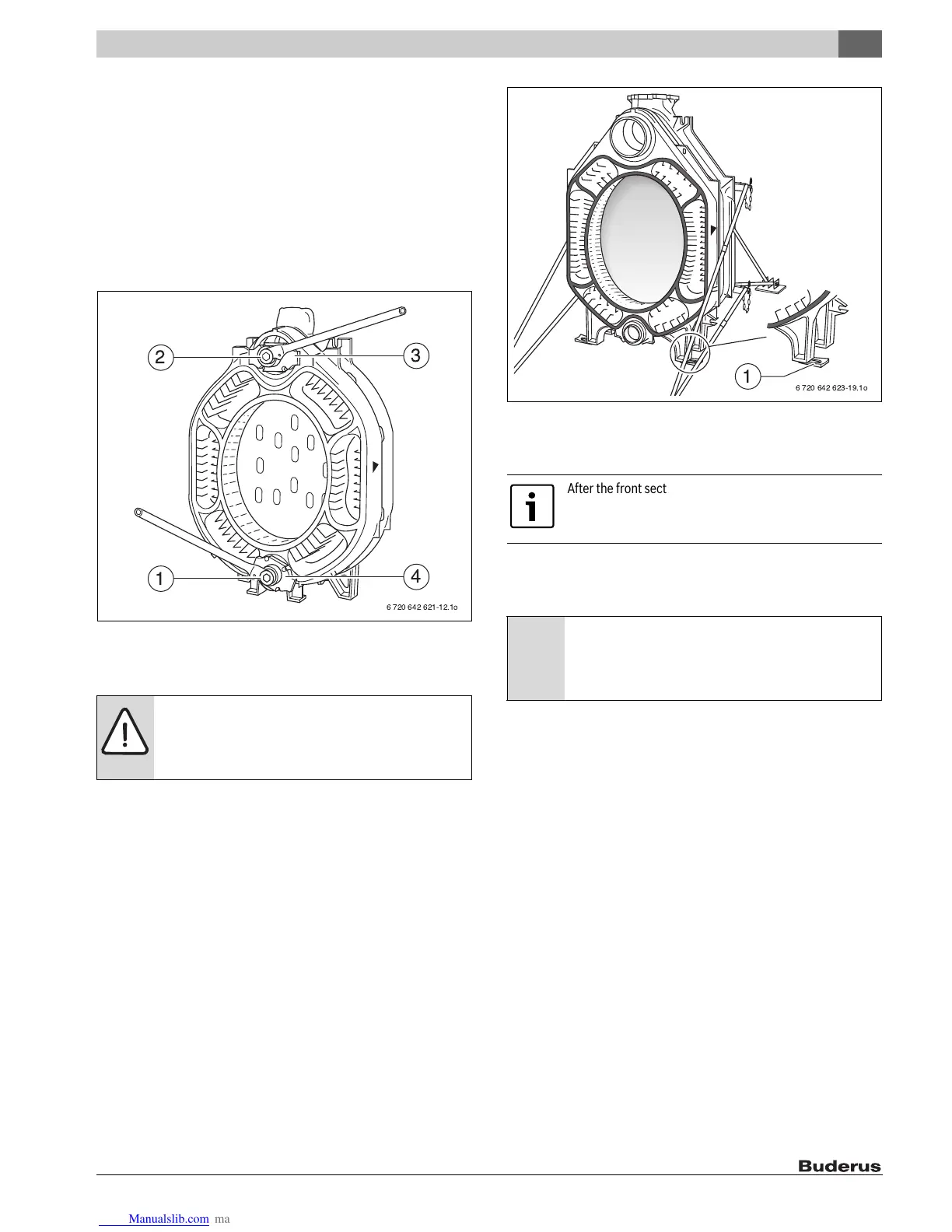
Assemble all other boiler sections as described. The front section is
fitted last.
▶ Insert the tie rods (with spring packs fitted) into the cast lugs on the
top left and right, and bottom left and right, next to the boiler hubs
( Fig. 22, [1 to 4]).
▶ Tighten the nuts hand-tight.
▶ Tighten the nuts on the tie rods 1 to 1½ turns.
▶ Level the boiler block vertically and horizontally on the base/
foundation ( see Chapter 6, page 11).
▶ Remove boiler assembly tool.
WARNING: Risk of injury from falling boiler sections.
▶ Remove the installation aid first if the partly-
assembled boiler consists of at least three boiler
sections.
After the front section is installed, loosen the assembly
tool – but do not remove it. Fit the tie rods first.
NOTICE: Damage to system through excessively low
contact pressure.
▶ Do not compress the spring pack. Only use the spring
pack in its original state.
 Loading...