7
Boiler block assembly
Logano G515 – 6 720 647 208 (2014/09)22
7.8.5 Insert the flue gas baffle plates
▶ Take flue gas baffles out of the fittings case and insert into the flue gas
passages as indicated by the inscription on them ( Fig. 34 and
Tab. 11).
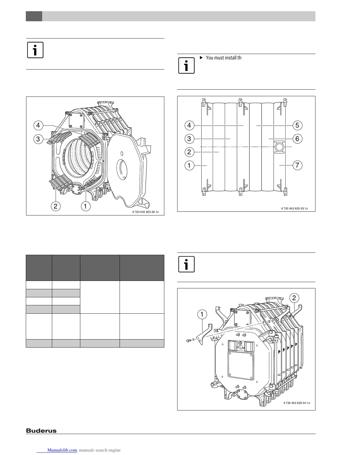
Fig. 34 Heat exchanger baffle plates
[1] Flue gas baffle plates (bottom right)
[2] Flue gas baffle plates (bottom left)
[3] Flue gas baffle plates (top left)
[4] Flue gas baffle plates (top right)
7.9 Installation of the boiler jacket
This section describes how to install thermal insulation and jacket
components.
Fig. 35 View from above: boiler block (7 boiler sections) with brackets
7.9.1 Mount the brackets
▶ Loosely screw the brackets for the boiler jacket onto the upper ribs of
the boiler sections on the left and right ( Fig. 35, Fig. 36 and
Tab. 12).
Fig. 36 Installing the mounting brackets
In pre-assembled boilers, the flue gas baffles are already
fitted.
▶ Remove the cardboard transport protectors from the
pre-assembled boiler.
Boiler
capacity
Number of
boiler
sections
Length of flue gas
baffle plate in
inches (mm)
Installation
information on the flue
gas baffle plate
( Fig. 34)
240 7 26 – 25/32 (680) top right
top left
bottom right
bottom left
295 8
350 9
400 10
455 11 16 – 47/64 (425) top right
top left
bottom right
bottom left
510 12 – –
Table 11
▶ You must install the cross rails and longitudinal rails
before installing the thermal insulation in order to be
able to align the brackets correctly.
▶ To install the thermal insulation, you need to take the
longitudinal rails off again in the following step.
▶ Screw the brackets on the rear section ( Fig. 36,
[2]) to the ribs from behind.
▶ Screw the brackets of the front and intermediate
sections ( Fig. 36, [1]) on from the front only.
6 720 642 623-33.1o
4
3
2
1
5
6
7
 Loading...