Nivotemp NT MD
4.2 Electrical connections
Electricity is supplied via plug connectors. Please refer to the appendix for installation dimensions, nominal voltage and plug
configuration.
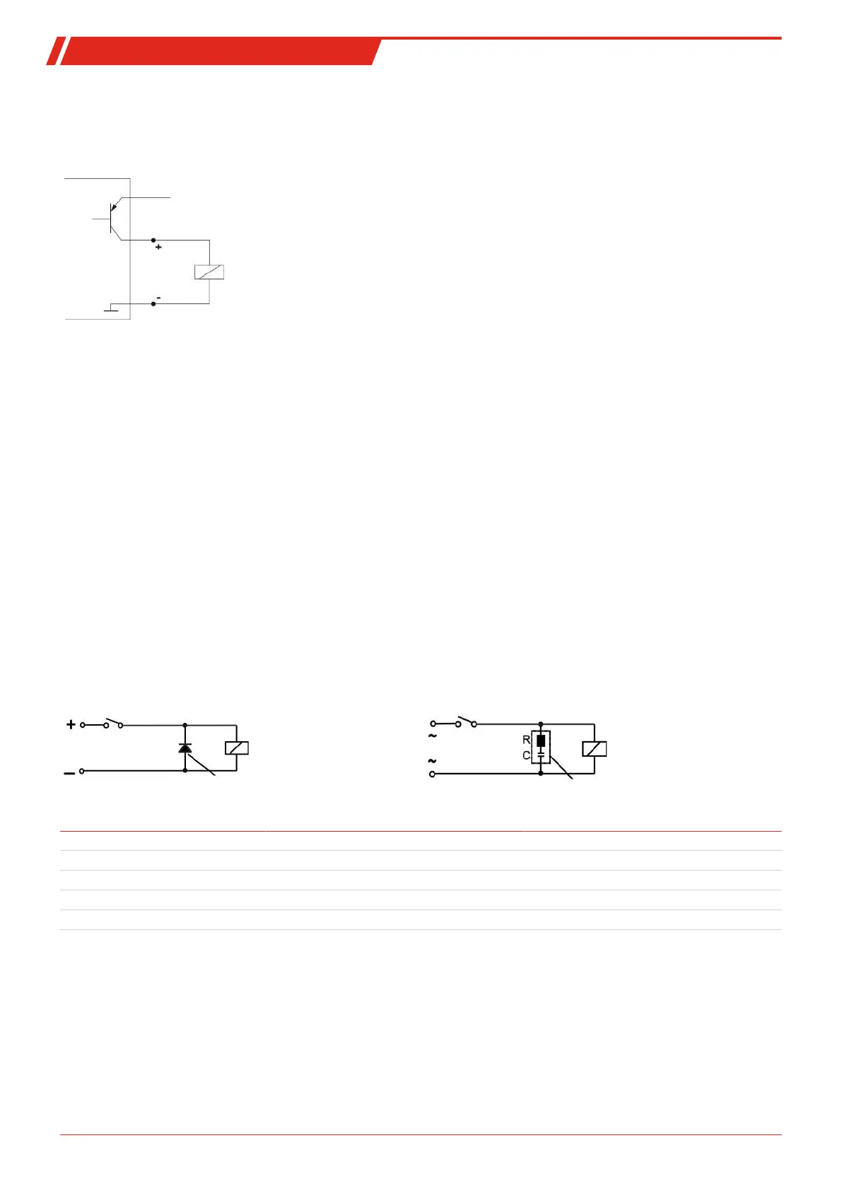
The temperature switching outputs are PNP transistors (see illustration):
Note:
When measuring the switching output with high-load measuring device inputs or when used as a frequency output, the
load must be set to 10 kΩ between the output and earth (GND) to avoid faulty measurements.
4.3 Information on the correct operation of reed contacts in Bühler level switches
Based on their construction, reed contacts are very long lasting and reliable components. Yet the following should be considered
when using them:
Life of reed switches
The life of reed switches can be up to 10
9
cycles. This is reduces by high stress and / or incorrect or the absence of protective cir-
cuits when switching inductive, capacitive or lamp loads.
It’s therefore important to ensure NEVER to exceed one or several of the maximum approved limits, even temporarily, and to
install a contact protective circuit for loads which are not purely ohmic. Using test lamps when installing the devices is also pro-
hibited, as these can temporarily allow too much current to flow, which can damage the reed contacts. In this case non-volatile
testing equipment should always be used.
Contact protective circuits for reed switches
For direct current voltage a recovery diode per figure A must be connected parallel to the contact.
For alternating current voltage an RC circuit per Figure B and Table 1 must be connected parallel to the contact.
A B
Load
Contact
Recovery diode
Load in VA 10 25 50
Voltage at contact V R/Ohm C/µF R/Ohm C/µF R/Ohm C/µF
24 22 0.022 1 0.1 1 0.47
60 120 0.0047 22 0.022 1 0.1
110 470 0.001 120 0.0047 22 0.022
230 470 0.001 470 0.001 120 0.0047
Please note the max. voltage/load ratings of the respective level contacts!
9Bühler Technologies GmbHBE100022 ◦ 11/2020


 To Next Page