LOWLANDER HD MK2 & WIDEBODY MANURE SPREADER – INSTRUCTION & SPARES MANUAL
Page 140
15.3 BOLT TORQUE
CHECKING BOLT TORQUE
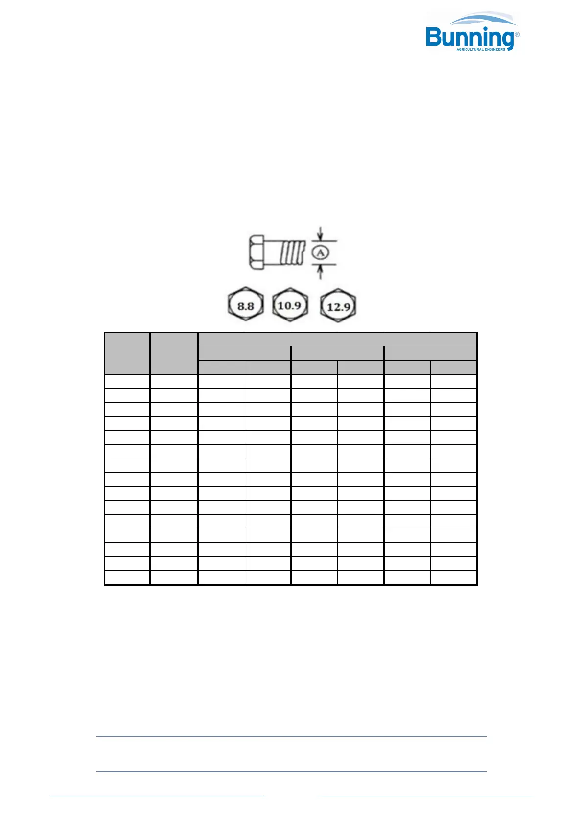
The table(s) shown below give correct torque values for various bolts and cap-screws. Tighten all bolts to
the torques specified in chart unless otherwise noted. Check tightness of bolts periodically, using bolt
torque chart as a guide. Replace hardware with the same strength bolt.
NOTE: Tighten the plastic insert (nylon lock) or crimped steel-type lock nuts to approximately 50% of the
dry torque shown in the chart, applied to the nut, not to the bolt head. Tighten the toothed or serrated-
type lock nuts to the full torque value.
METRIC TORQUE SPECIFICATIONS
(N.m) (lb-ft) (N.m) (lb-ft) (N.m) (lb-ft)
M3 5.5 0.5 0.4 1.8 1.3 2 1.5
M4 7 3 2.2 4.5 3.3 5 4
M5 8 6 4 9 7 10 7.5
M6 10 10 7 15 11 18 13
M8 13 25 18 35 26 45 33
M10 16 50 37 70 52 85 63
M12 18 90 66 125 92 150 111
M14 21 140 103 200 148 240 177
M16 24 225 166 310 229 370 273
M18 27 305 225 435 321 510 376
M20 30 435 321 610 450 725 535
M22 33 590 435 840 620 985 726
M24 36 750 553 1050 774 1255 926
M30 46 1495 1103 2100 1550 2490 1837
M36 55 2600 1917 3675 2710 4280 3157
Bolt
Diameter
"A"
Wrench
Size (mm)
Bolt Torque*
Bolt G8.8 (Nut G8) Bolt G10.9 (Nut G10) Bolt G12.9 (Nut G12)
Torque figures indicated above are valid for non-greased or non-oiled threads and heads unless otherwise
specified. Therefore, do not grease or oil bolts or cap-screws unless otherwise specified in this manual.
When using locking elements, increase torque values by 5%. Reduce value by 10% if threads are oiled
before assembly.
* Torque value for bolts and cap-screws are identified by their head markings.
**Always install new or unused locking nuts whenever possible or practical to ensure the full locking
benefit.
This manual must stay with the machine/operator at all times.
This manual is an original English language copy.



 To Next Page