LOWLANDER HD MK2 & WIDEBODY MANURE SPREADER – INSTRUCTION & SPARES MANUAL
Page 81
6.3.6 RELSV SETTING INSTRUCTIONS
The RELSV is probably the most important part of the trailer’s braking system, whether ABS is fitted or not. A poorly
set up RELSV can be both dangerous and expensive.
Too little output pressure leads to under braking, and this could result in a jack-knife.
Too much pressure can cause the trailer to lock, and “swing” passed the tractor. Also, too much pressure causes
premature and expensive trailer tyre wear.
Periodically it is worthwhile checking the RELSV output pressures and making sure they match the suspension
correctly. To do this properly you will require two gauges, a tape measure, calculator and a little patience!
Step 1
Have the trailer completely laden (the maximum weight allowed) and stand it on level ground whilst still connected to
the tractor. If the RELSV is connected to one axle, then measure the distance between the top of this axle and the
underside of the chassis (If the trailer is fitted with a bar between the axles, then you can measure the distance above
each axle and halve the total).
Step 2
Remove the load completely and repeat the same measurements as taken above. The difference between these two
measurements is the “unladen to laden spring deflection”. For this example, we shall assume it was 25mm.
Step 3
Find out the recommended unladen LSV setting pressure for your trailer. This may be on a data plate, or available
from GT Bunning, or J H Milnes, the air kits supplier.
This is not the pressure present in the trailer’s brakes during normal unladen braking, but is a pressure used for
setting up the RELSV!
Along with this unladen pressure you should also get its associated “test pressure”, as well as the laden brake
pressure.
Typically, these could be 6.0 bar (Test) 2.5 bar (Unladen) and 6.0 bar (Laden). If you cannot get access to the actual
test pressures for your trailer, then the above figures may be close enough.
Step 4
Calculate the “regulating ratio”.
An acceptable way of doing this is by dividing the test pressure by the unladen pressure.
Using the example above, this would be 6.0 divided by 2.5 = 2.4
Step 5
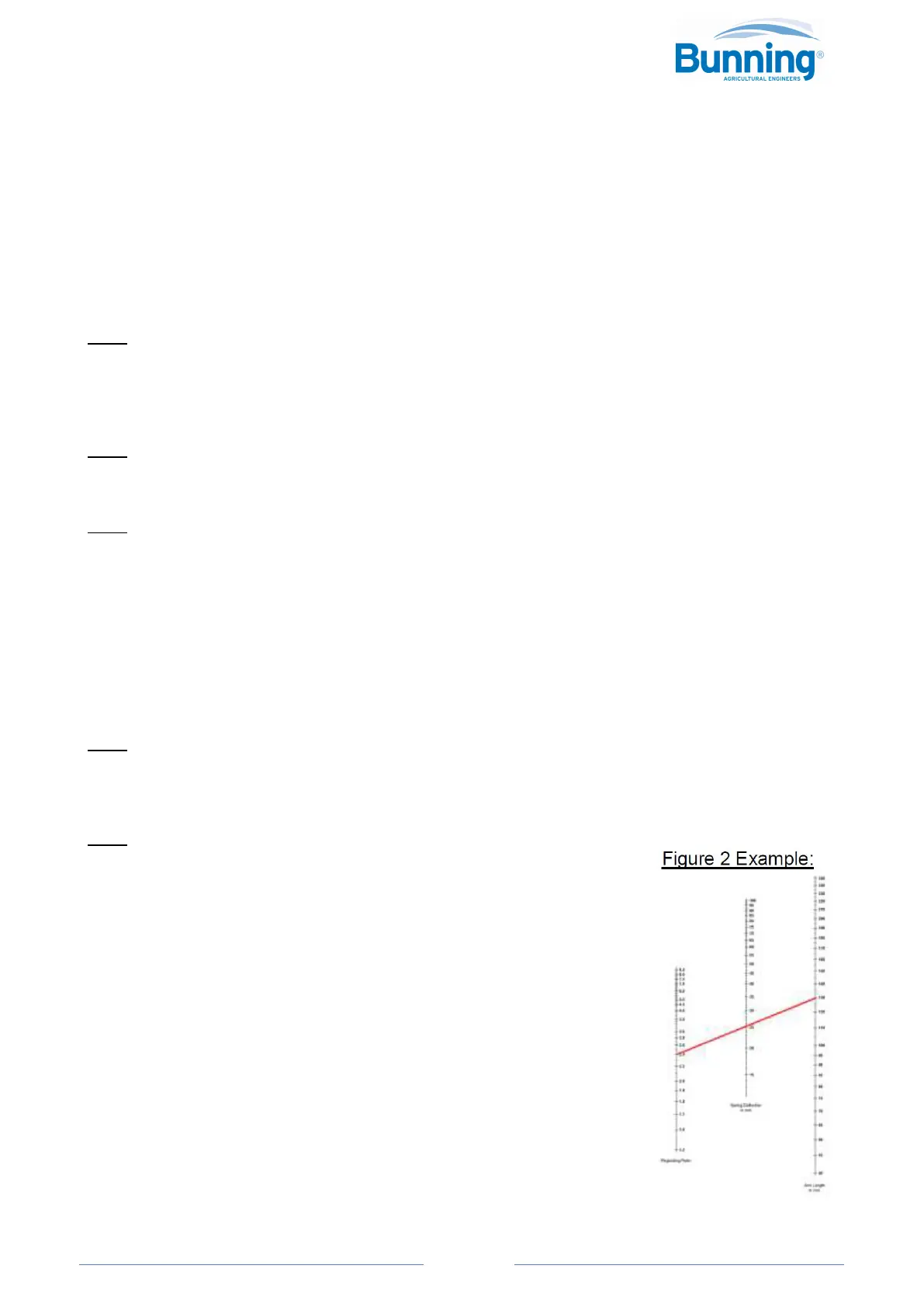
Look at the graph (Figure 2 below) and find the point on the left-hand column which
relates to the regulating ratio (2.4) which you have just calculated. Mark that point.
In the central column find the point which relates to your unladen to laden spring
deflection, which you measured in Step 2 (25mm). Mark that point.
Draw a straight line from the point you marked in the left column, through the point in
the second column, and extend this line until it crosses the right-hand column.
Where it crosses this column read off the measurement, as this is the correct RELSV
arm length for this trailer. This length is measured from where the arm connects to the
RELSV (centre of the securing bolt head) and the point where the rubber linkage fits on
the other end.
Adjust the arm length on the valve accordingly and tighten the securing bolt.