E-12-
1067
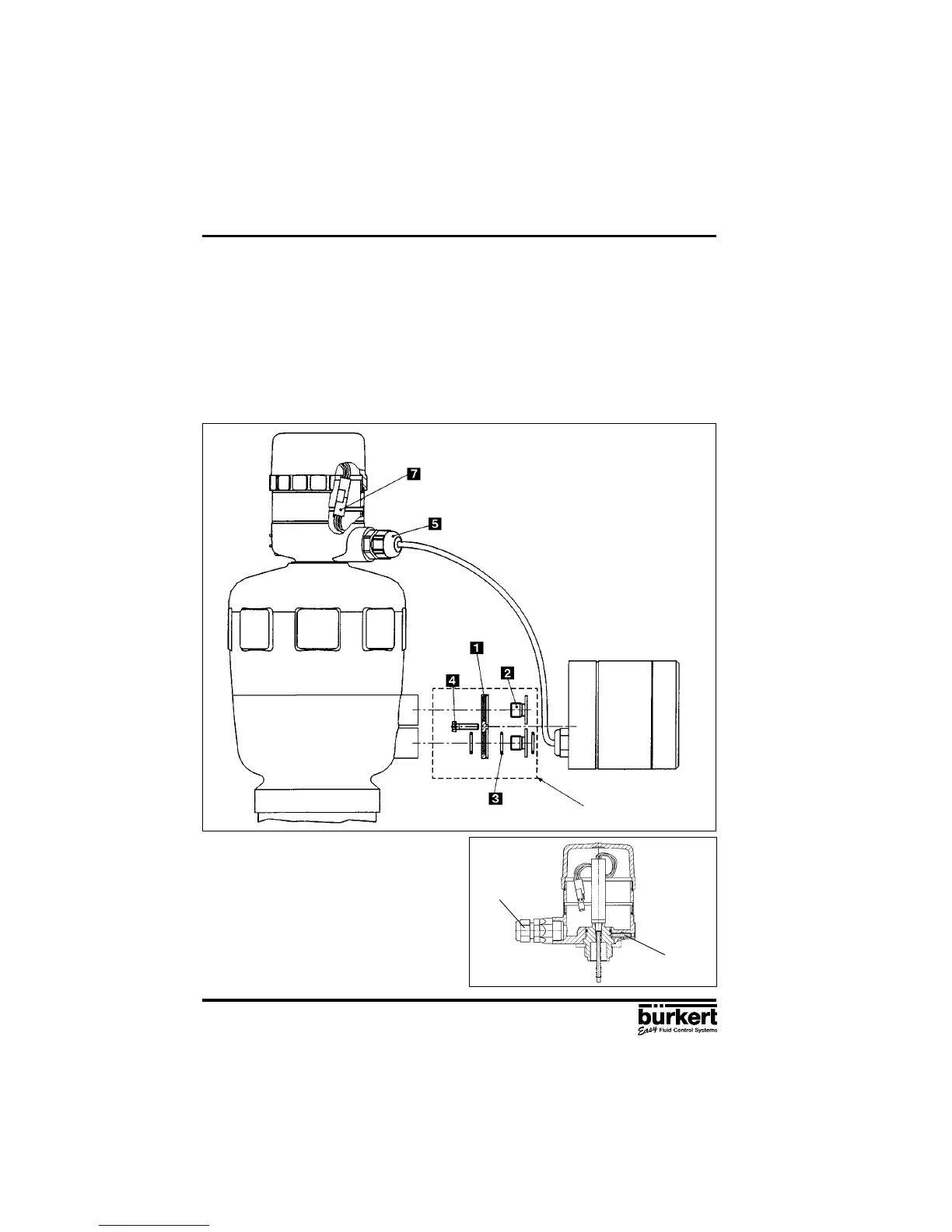
POSITIONER TYPE 1067
Fig. 14 External feedback/positional
transducer
3 INSTALLATION
Set of add-on parts for
Bürkert piston drive (ø125)
Set path-measuring system directly on the drive from above. Great care must be taken to ensure that
the spindle of the path-measuring system is seated on the spindle of the drive.
Screw in the path-measuring system and secure with spanner.
Loosen setscrew and turn feedback/positional transducer so that the cable outlet is in the desired
position. Retighten setscrew.
Unscrew lid of path-measuring system. Remove PG-threaded joint from the housing of the path-
measuring system. Lead the plug of the positioning cable through and plug it into the housing of
the path-measuring system (green to green, white to red, brown to yellow). Draw surplus cable
inwards, tighten PG threaded joint. Screw lid back on (O-rings).
Fig. 13 Diagram for the assembly of positioner and external path-measuring system to a Type
2031 continuous valve with piston drive (conforming to NAMUR)