1067
POSITIONER TYPE 1067
E-11-
Fig. 11 Fitting to a type 2031 continuous
valve with piston drive
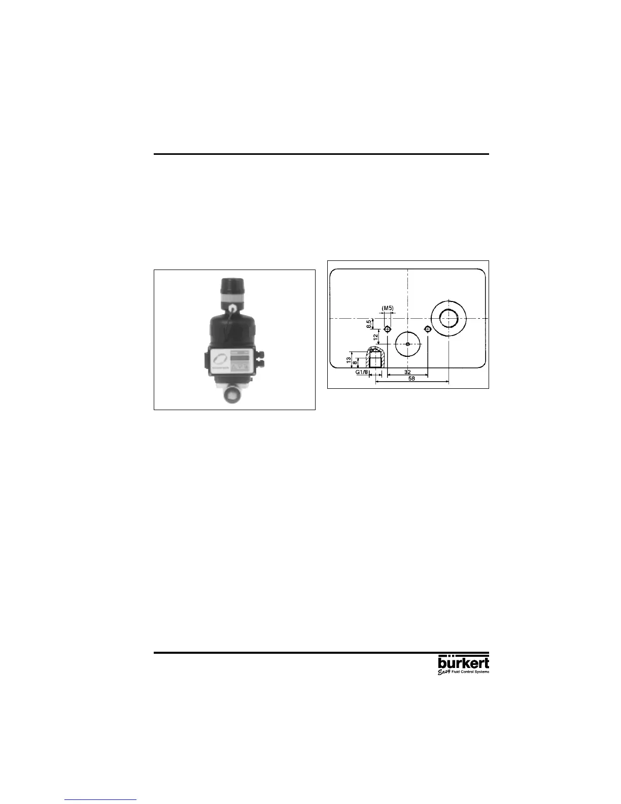
Fig. 12 Rear view of positioner (variant 2)
Assembly
Assembly of variant 2 of the positioner to a type 2031 continuous valve with piston drive.
A set of add-on parts (NAMUR adapter, Fig. 13) is provided for assembling variant 2 of the positioner
to a piston valve (e.g. type 2031). It consists of a mounting plate , two hollow bolts , three O-rings
and two cheese-head bolts M5 .
To assemble the positioner on a type 2031 continuous valve with piston drive, the following steps
should be carried out (Fig. 13):
Place an O-ring in the recess of the mounting plate (drive side). In the case of a large version,
place a second O-ring on the other side of the mounting plate.
Put two cheese-head bolts M5 from the drive side through the 5-mm drillings in the mounting plate.
Screw the preassembled mounting plate to the two connection pieces of the valve drive with two
hollow bolts so that the lower connection piece is sealed by the O-ring.
Place an O-ring in the groove on the reverse side of the positioner.
Add the positioner to the mounting plate and screw it on with the two cheese-head bolts .
Assembly of the external feedback/positional transducer to a type 2031 continuous valve with piston
drive.
To assemble the external feedback/positional transducer, the following steps should be carried out
(Figs. 13 and 14):
Check that an O-ring has been put into the valve drive (top). Insert O-ring if necessary.
3 INSTALLATION
3.1.2 Fitting the positioner to a type 2031 continuous valve with piston drive
Arrangement
In the case of a continuous valve with piston drive, variant 2 with the external path-measuring system
(Fig. 3) should be used. The positioner is placed on the valve and screwed to it (Figs. 11 and 12). The
valve position is transmitted directly via the spring-mounted rod of the path-measuring system (the
linear potentiometer).