E-6-
1067
POSITIONER TYPE 1067
2 DESCRIPTION
2.3 Principle of operation
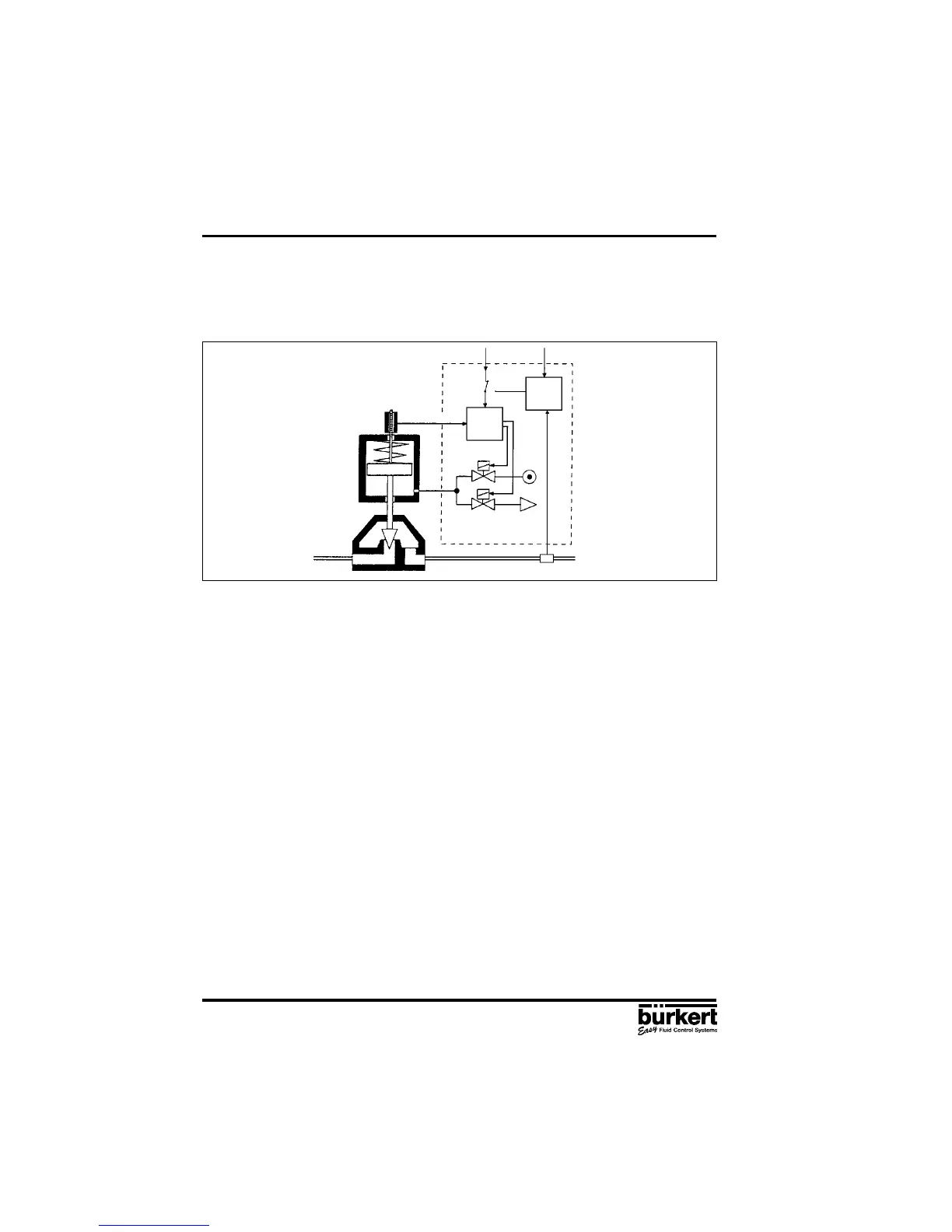
Fig. 4 shows a operational diagram of the positioner with its relationship to a piston drive control valve.
An external feedback/positional transducer is used in this case to measure the actual position.
Fig. 4 Operational diagram
Piston
valve
Air inlet
Solenoid valves
Air exhaust
Position
controller
Set
position
Process value (Pressure, flow, level...)
Sensor
Process
controller
The position (actual position) of the valve drive is determined by the feedback/positional transducer.
The signal corresponding to the actual position is continuously compared in the positioner with the
desired position and the error (control deviation) is formed. Pulses of variable duration corresponding
to the error are delivered to the magnetic valves of the electropneumatic system, by means of which
the supplied air and outgoing air for positioning the actuating drive of a continuous valve are controlled.
The desired position can be preset either via a standard signal input from outside (e.g. manually or
via an external controller) or via the internal process controller. In the latter case, the desired process
value is applied to the standard signal input or entered via keypad and a comparison is made with
the process quantity (e.g. flow, pressure, level or temperature) that is to be controlled (Fig. 4).
If the desired position is preset externally via the standard signal input provided for that purpose (i.e.
if the internal process controller is not used), the device works as a position controller only (Fig. 5).
The position controller is implemented as a PD controller within the microprocessor. A pulse-width
modulation (PWM) member is connected to the controller output and, via its B
1
and E
1
outputs, the
magnetic valves for supplying air to and venting the actuating drive are controlled. When a positive
error exists, pulses (PWM signals) are output from output B
1
to switch the supplied air. When a
negative error exists, pulses are output from output E
1
to switch the outgoing air.
The positioner can be supplied for both single-acting and double-acting actuating drives. The PWM
member has two further outputs, B
2
and E
2
, via which the two additional magnetic valves for supplying
air to and evacuating air from double-acting actuating drives are controlled.
If the internal process controller is used, it constitutes a component in a higher-level control loop
(main control loop). The position controller mentioned above now operates in a lower-level auxiliary
control loop. The overall effect is sequence control (Fig. 6). The internal process controller (main
controller) is implemented as a PID controller (Z1 and Z2 representing disturbance variables).
Feedback/positional
transducer
Actual-position
External setpoint
Process
setpoint