1067
POSITIONER TYPE 1067
E-13-
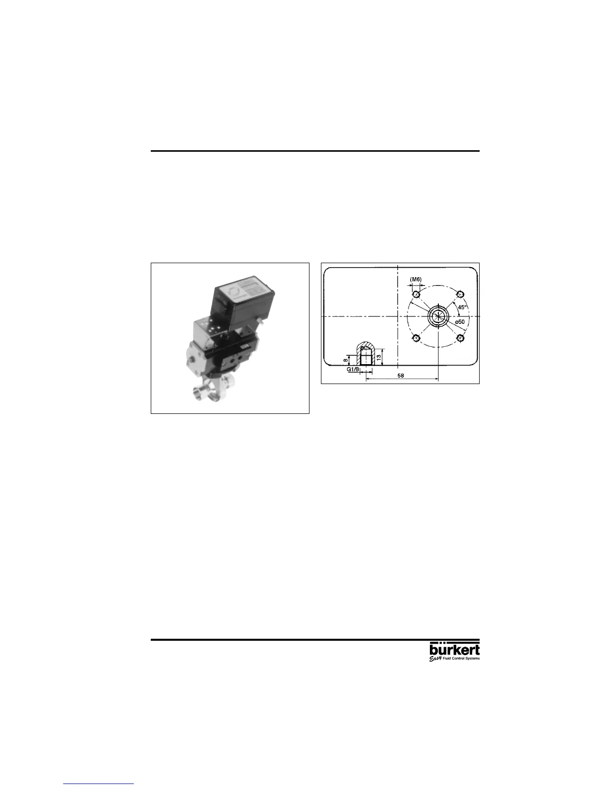
Fig. 15 Fitting to a continuous valve with
rotary drive
Fig. 16 Reverse side of positioner (variant 1)
with securing holes
3 INSTALLATION
Assembly
A coupling (adapter) is provided for assembling variant 1 of the positioner on to a continuous valve
with a rotary or part-turn valve actuating drive (e.g. Type 3210, Fig. 17). In addition, an assembly clip
(Fig. 18) is required and can be obtained from the manufacturer of the part-turn valve actuating
drive. (It is normally used for the assembly of a limit-switch box).
To assemble, the following steps should be carried out (Fig. 18):
Secure the assembly clip to the valve drive.
Place the coupling on the shaft of the positioner’s feedback/positional transducer. The setscrew
on the coupling should first have been slightly withdrawn.
Place the positioner on the assembly clip. Ensure that the flat piece of the coupling fits into the slot
in the end of the drive shaft.
Secure the positioner on the assembly clip with 4 x M6 screws.
Fix the coupling to the shaft of the feedback/positional transducer by screwing in the setscrew .
If after the AUTOTUNE function is started the message TURN POT is displayed on the LCD, the
setscrew must be loosened and the shaft of the path-measuring system rotated 180° relative to the
drive. The setscrew should then be screwed tight and the AUTOTUNE function repeated.
3.1.3 Fitting the positioner to a continuous valve with rotary drive
Arrangement
In the case of a continuous valve with rotary or part-turn valve actuating drive, variant 1 with an
internal feedback/positional transducer should be used. Its shaft is coupled to the valve rotary drive
(e.g. flap valve). The position of the rotary drive is thus transmitted directly to the shaft of the
feedback/positional transducer.