english
Operating Instructions-No. 803 150
13
3 GENERAL DESCRIPTION
3.1 Valve Construction
• 3/2 way pilot valve with various electrical connection possibilities
• the top-mounted coil can be locked in 4 x 90° steps, for optional positioning in between
around the core guide tube
• valve body with diaphragm and seat seals (3/2 and 5/2), or with gate valve (5/3)
• working connections 2 (B) / 4 (A) and supply and ventilation connections 1 (P) / 3 (S) /
5 (R) with G 1/4 internal thread or plug connection for 8 mm hose external diameter
• the valves can be mounted on the modular pneumatic basic rail Type MP07
• can be mounted in any position, preferably with the magnetic system at the top
the valves are also available in explosion-proof versions
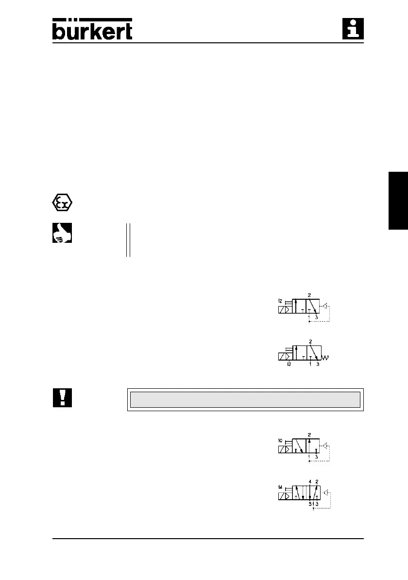
3.2 Valve operations of the Type 6518 / 6519
3/2 way valve:
In de-energised position, Pressure Inlet 1 closed,
Outlet Port 2 exhausted
3/2 way valve for vacuum, with auxiliary pilot air:
In de-energised position, Pressure Inlet 1 closed,
Outlet Port 2 exhausted
The vacuum generator must be connected to port 1!
3/2 way valve:
In de-energised position, Pressure Inlet 1 connected
to Outlet Port 2
5/2 way valve:
In de-energised position, Pressure Inlet 1 connected
to Outlet Port 2, Outlet Port 4 exhausted.
ATTENTION!
NOTE Plug-in connections only for the service ports 2 (B) and 4 (A).
The valves require no maintenance.