english
17
Operating Instructions-No. 803 150
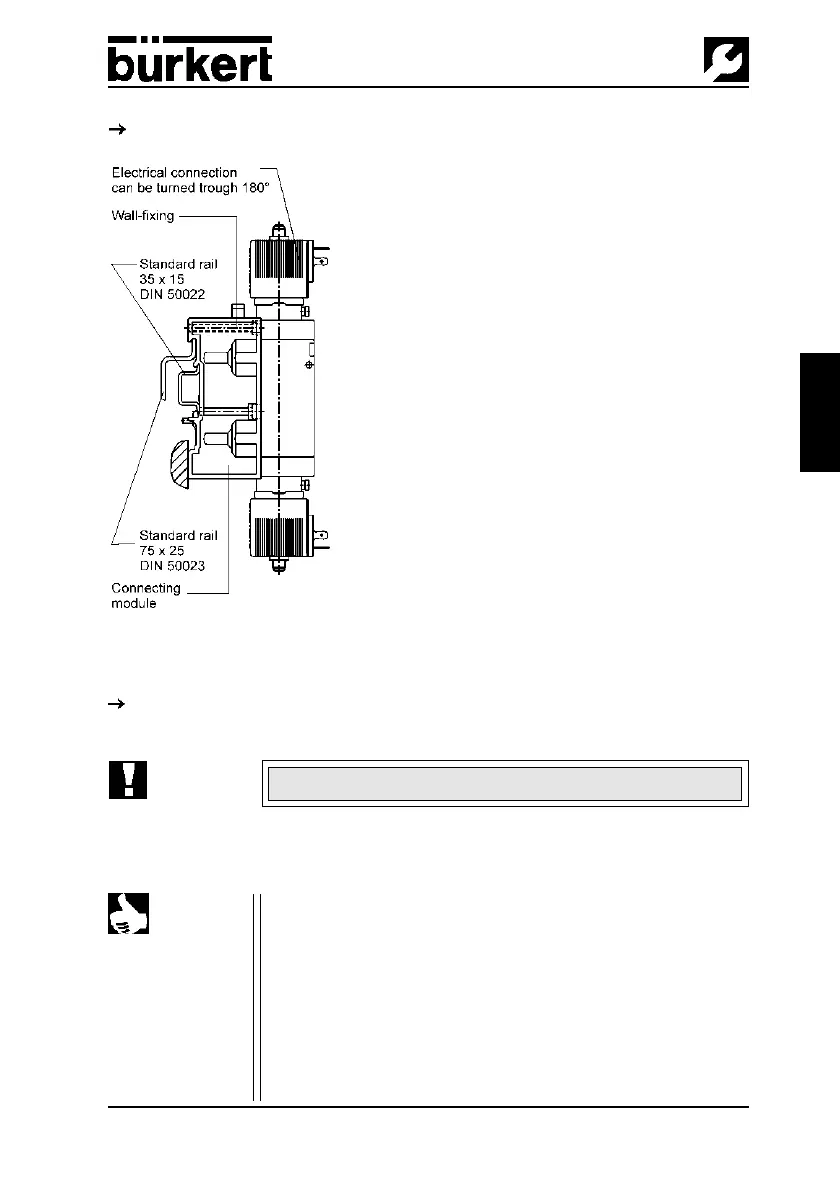
4.4.2 Wall mounting
Fix the module system directly to the wall using M5 screws.
4.5 Mounting single valves (Fig. 3)
Fix the single valve directly to the wall using M4 screws.
ATTENTION!
NOTE For plug-in connections, the hose lines must meet the following
requirements:
• Minimum rigidity of 40 Shore D (to DIN 53505 or ISO 868);
• External diameter corresponding to DIN 73378 (max.
permissible deviation ± 0.1 mm from nominal dimension);
• Without burr, cut at right-angles and with undamaged
circumference;
• The hose lines must be pushed into the plug-in connectors up
to the stop.
4.5.1 Plug-in connections
When mounting, do not distort the valve body!
Figure 2: Mounting the valve block