19
Technical data
Type 8710, 8711, 8713, 8715
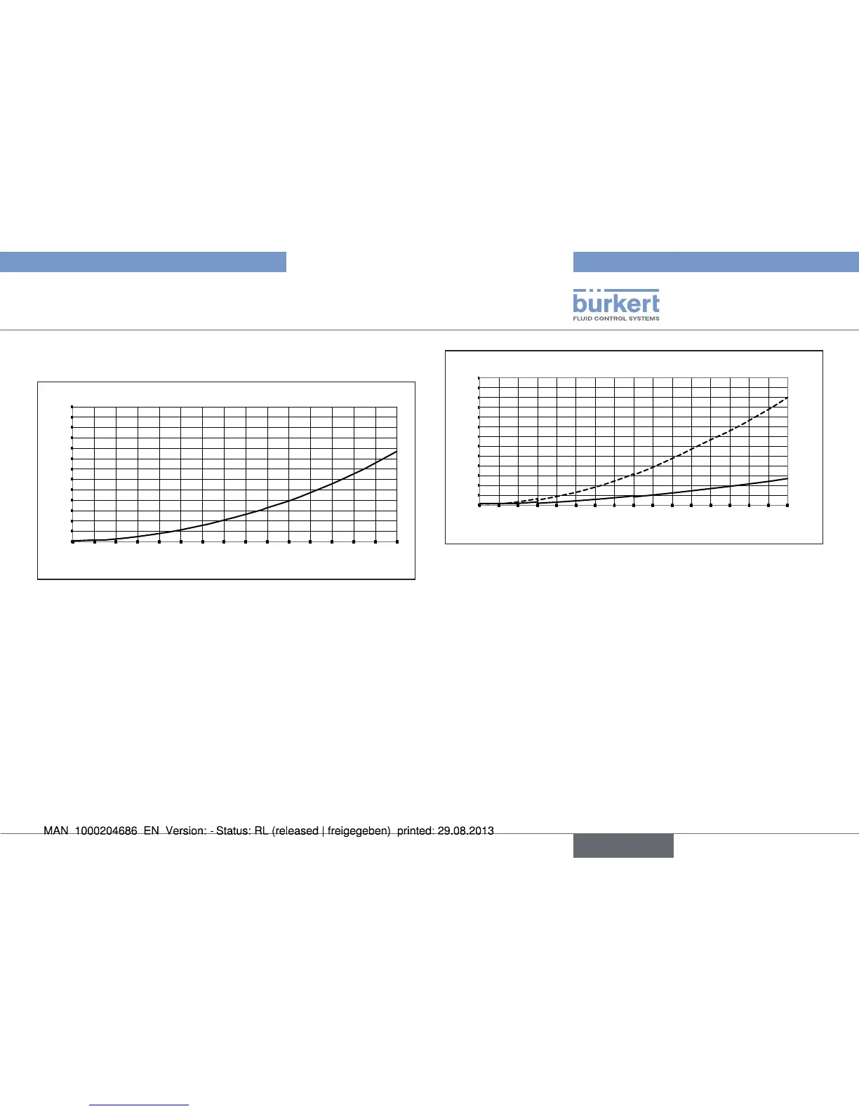
6.6.3. Pressure loss characteristics
Q [l
N
/min]
p [mbar]
0
10
20
30
40
50
60
70
80
90
100
110
120
130
012345678910 11 12 13 14 15
1/4''
Fig. 14: Pressure loss diagram (reference air, with a 250 µm inlet
mesh filter), types 8700 / 8705
The diagram shows exemplarily the pressure loss characteristics
when air flowing through.
For determining the pressure loss with another gas first calculate the
air equivalent of the other gas.
0
10
20
30
40
50
60
70
80
90
100
110
120
130
0510 15 20 25 30 35 40 45 50 55 60 65 70 75 80
Q [l
N
/min]
flange
1/4''
Fig. 15: Pressure loss diagram (reference air, with a 250 µm inlet
mesh filter), types 8701 / 8703
The diagram shows exemplarily the pressure loss characteristics
when air flowing through.
Further it differentiates two designs, first one with ¼ inch connectors
and second one with connections on the bottom of the flowmeter
(used for assembly on manifolds).
For determining the pressure loss with another gas first calculate the
air equivalent of the other gas and respect the fluidics needed with
the other gas.
English