23
Installation and commissioning
Type 8710, 8711, 8713, 8715
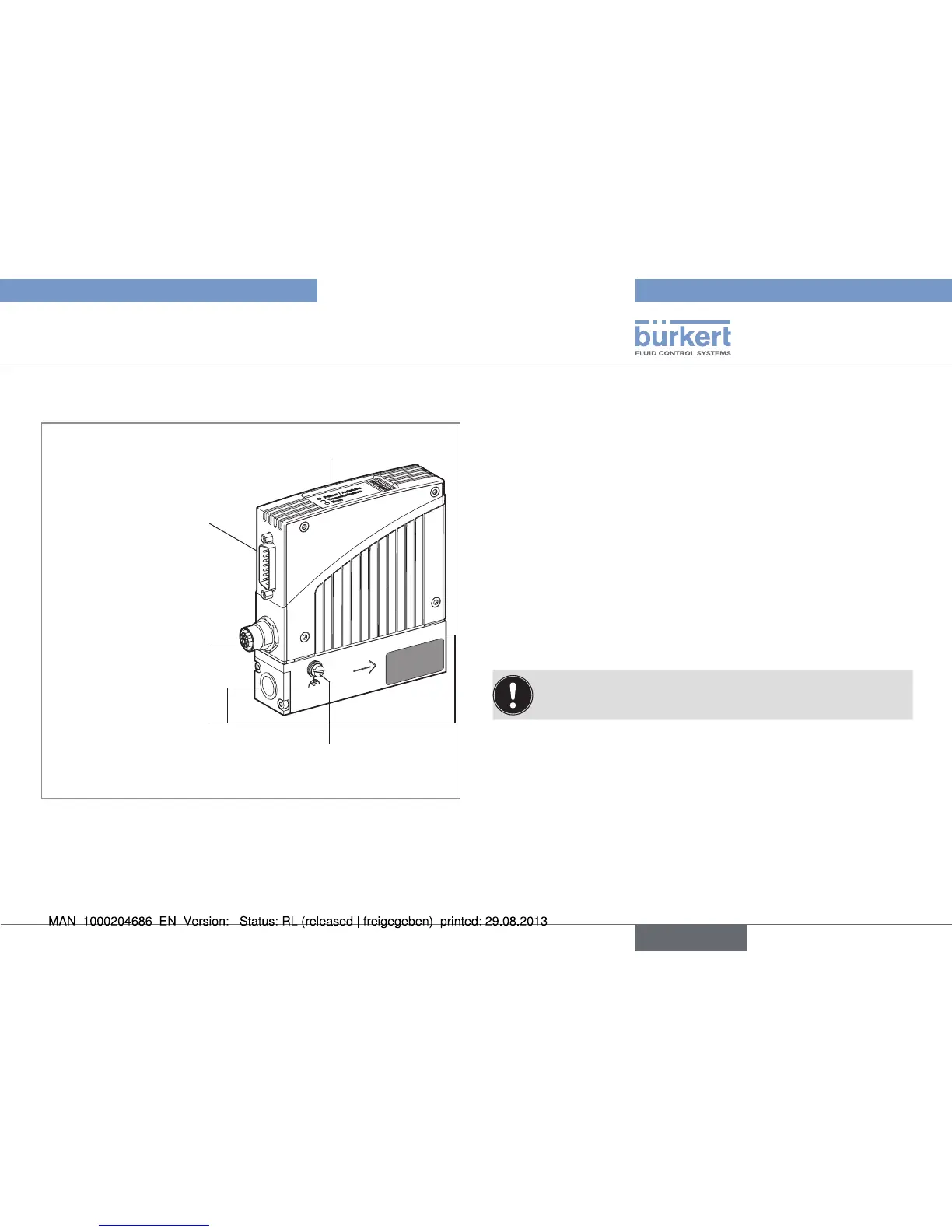
7.3. Description of the MFM / MFC
LEDs
Sub-D 15-pin base Set-
point input /
Measured flow-rate
output /
Binary inputs / RS232
Screw for earth
connection
5-pin round base
24 V supply /
Relay outputs
Connection
to the line
Fig. 16: Description of the MFM / MFC
7.4. Sequence of the steps to be
performed
1. Mechanical installation
2. Fluid installation
3. Electrical installation
4. Set the device parameters
5. Pressurize the lines with operating fluid
6. Flush and completely deaerate the lines with operating fluid at
the calibration pressure
7.5. Setting the parameters
7.5.1. Setting the bus address
To ensure trouble-free setting, reset the device by switching
off the power supply to the device.
The bus address of the device can be set either via the Bürkert
configuration tool "Mass Flow Communicator" in the "Views" window
→ PROFIBUS / DeviceNet / CANopen or directly via the master bus.
The address must be reinitialized after a change on the slave and on
the master. It may be necessary, depending on the bus, to send a
corresponding telegram.
English