21
Technical data
Type 8710, 8711, 8713, 8715
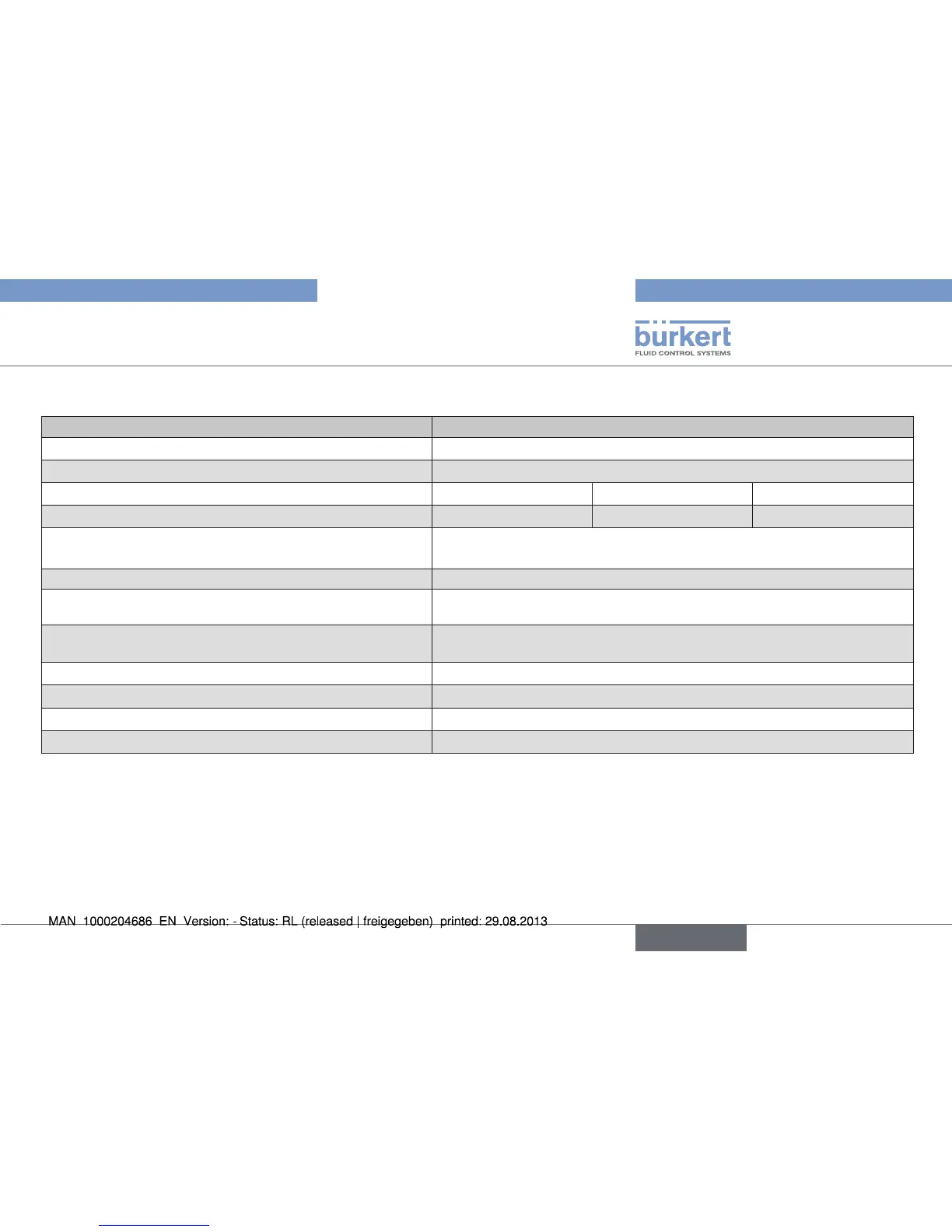
6.7.2. Electrical data for types 8700 / 8701 / 8710 / 8711
Specification Type
Power supply 24 V DC ± 10%; residual ripple < 2% (5% for UL devices)
Power supply (not provided) for UL devices Power supply limited to class 2
Type of device 8700 / 8701 8710 8711
Power required (max. in Watt) 5 10 14
MFC 8710 and 8711 only:
Analogue input (configurable)
• 0/4 - 20 mA, input impedance max.: 300 Ω, resolution : 5 µA
• 0 - 5/10 V, input impedance min. : 20 kΩ, resolution: 2.5 mV
Binary inputs (configurable) 2, active at the trailing edge, to be connected to DGND for activation
Analogue output (configurable) • 0/4 - 20 mA, max. load: 600 Ω, resolution: 20 µA
• 0 - 5/10 V, max. current: 10 mA, resolution : 10 mV
Communication interface
(alternative to analogue input + output)
PROFIBUS DP V1, DeviceNet or CANopen
Relay output (configurable) 1, potential-free changer, 60 V, 1 A, 60 VA
LEDs (configurable) 3 LEDs, status display for Power, Communication or Limit, Error
Electrical connections Sub-D 15-pin male fixed connector
Additional connections for version with field bus M12 5-pin female or male fixed connector
English