22
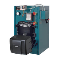
b. Remove existing nozzle from nozzle
adapter.
c. Insert the proper NOZZLE into NOZZLE
ADAPTER and tighten securely (Do not
over tighten).
d. Replace adapter, with nozzle installed, into
drawer assembly and secure with screw (1).
iii. Inspect/Measure Burner Electrodes.
Refer to Figure 11C.
iv. Re-install Drawer Assembly into
Combustion Head. Refer to Figure 11B.
v. Check Insertion Depth. Verify the distance
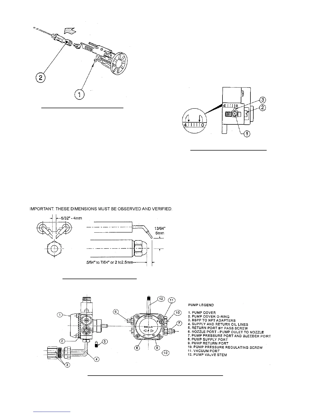
Figure 11C: Electrode Setting
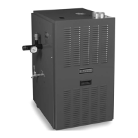
Figure 11D: Turbulator Setting
Figure 11E: Pump Connections and Port Identication
Figure 11B: Nozzle Replacement
between the tip of the end cone to face of the
burner mounting ange is as specied in
Table 8A “Riello Burner Specications” at
rear of this manual.
vi. Verify Turbulator Setting, Refer to Figure
11D.
a. Conrm the turbulator setting is as specied
in Table 8A “Riello Burner Specications”
of this supplement.
b.`If adjustment required, loosen RETAINING
NUT (1), then, turn SCREW (2) until the
INDEX MARKER (3) is aligned with the
correct index number shown in Table 8A
“Riello Burner Specications” at rear of this
manual.
c. Retighten the RETAINING NUT (1) upon
adjustment completion.
MODEL F5 NOTE: Zero and Four are scale
indicators only. From left to right the rst
line is four (4) and the last line is zero (0).
vii. Pump Connections and Port
Identication, Refer to Figure 11E.
This burner is shipped with the oil pump
set to operate on a single line system. To
operate on a two-line system the bypass
plug must be installed.

 Loading...