28
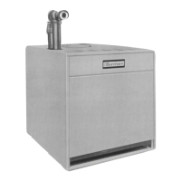
Figure 14: Left Side Canopy Intermediate Bracket
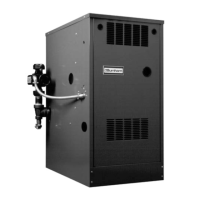
Figure 15: Right Side Canopy
Intermediate Bracket
c. Secure canopy left side bracket(s) with
appropriate canopy ‘J’ bolt(s). Insert threaded
end through holes in brackets and hook ‘J’ bolt
on center section draw-up rod (hooks should face
outward). Secure canopy with 5/16″ at washers,
lock washers and brass nuts. See Figure 14.
d. Secure canopy right side bracket(s) with ¼ -
20 x 5″ lg. carriage bolts. Insert head of carriage
bolt between canopy body and casting. Slide
carriage bolt into slot provided between castings.
Lower carriage bolt until threaded end will pass
through hole in bracket. Secure canopy with ¼″
at washers, lock washers and brass nuts. See
Figure 15.
13. Attach the 1/8″ x 1″ wide self-adhesive ber gasket
to the surfaces of either the top ue outlet damper
assembly or top outlet canopy cover that mounts
against the canopy. Gasket must be centered over
all attachment holes. Do not overlap corners, cut
butt joints.
14. Secure either the top ue outlet damper assembly
or top outlet canopy cover with #10 x 1/2″ sheet
metal screws.
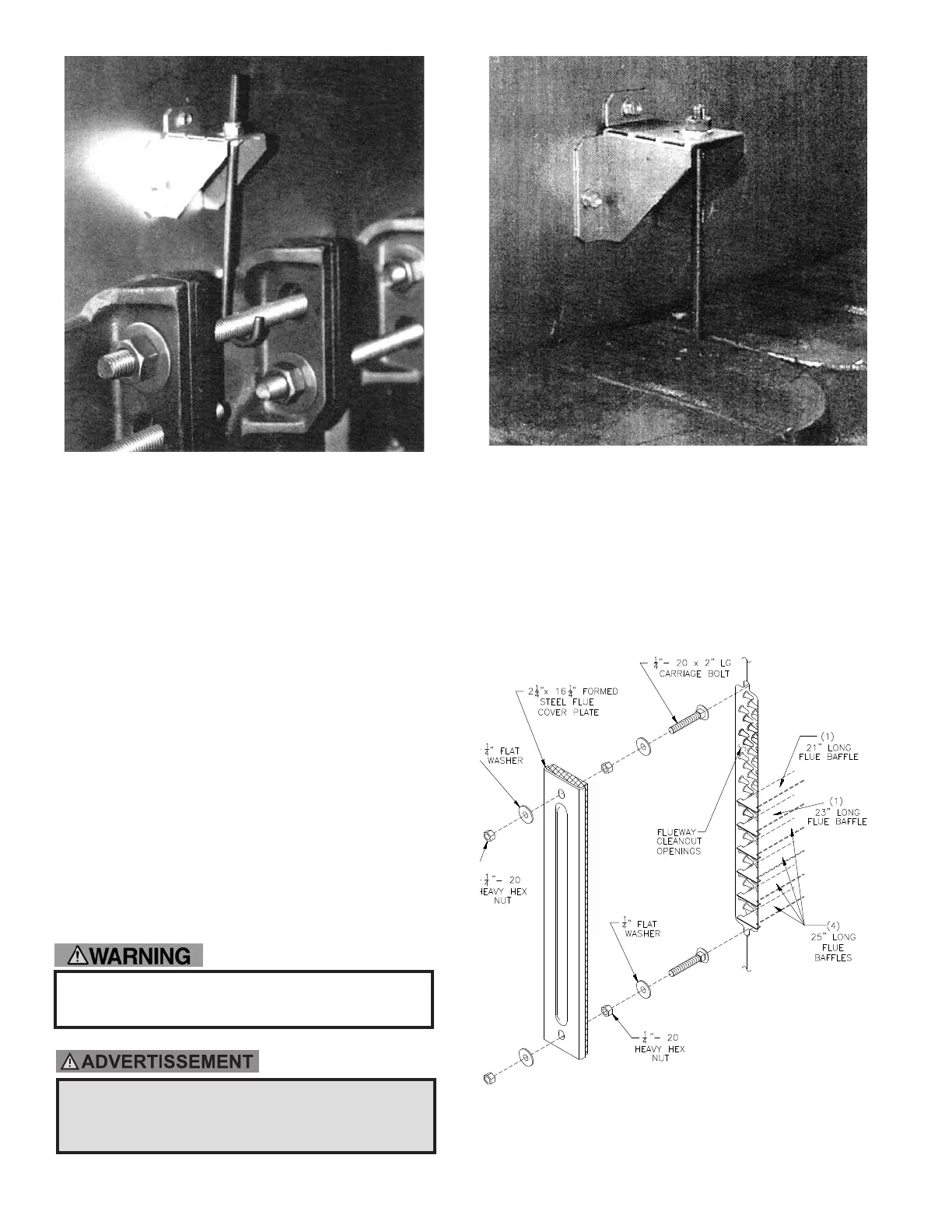
B. INSTALL FLUE BAFFLES AND COVER PLATES
over cleanout openings on left side of boiler as shown
in Figure 16.
1. Locate the ue bae carton. Each ue opening will
get four (4) 25” baes, one (1) 23” bae, and one
(1) 21” bae.
Figure 16: Flue Cover Plate Attachment
See Important Product Safety Information on Page 7 of
this manual, regarding refractory ceramic ber product
warning.
Reportez-vous aux Informations importantes sur la
sécurité du produit à la page 7 de ce manuel concernant
l'avertissement concernant les produits en bre de
céramique réfractaire.
 Loading...