33
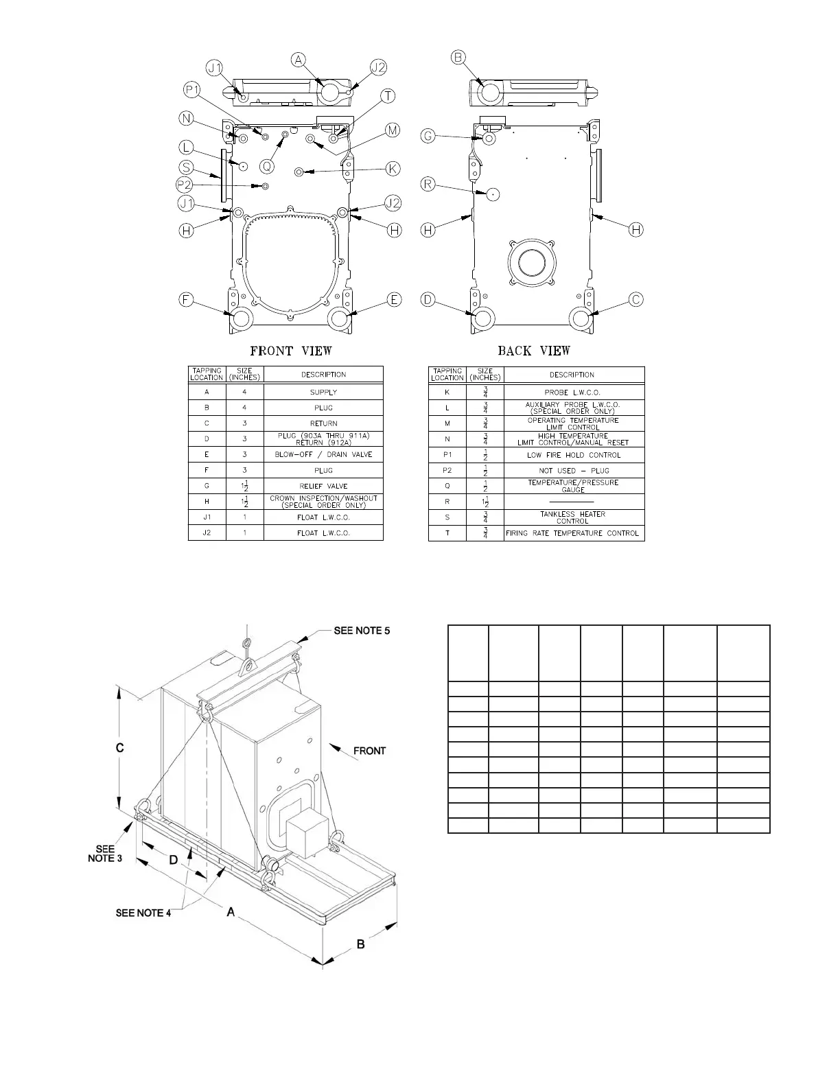
Figure 21: Purpose of Tappings
Boiler
Model
Number
of
Sections
Length
A
Width
B*
Height
C**
Approx.
Center of
Gravity
D***
Approx.
Shipping
Weight
LBS***
V903A 3 63-5/8 34-1/2 61 17-1/2 1478
V904A 4 69-5/8 34-1/2 61 20-1/2 1790
V905A 5 75-5/8 34-1/2 61 23-1/2 2102
V906A 6 81-5/8 34-1/2 61 27-1/2 2418
V907A 7 87-5/8 34-1/2 61 30-1/2 2734
V908A 8 93-5/8 34-1/2 61 33-1/2 3071
V909A 9 105-5/8 34-1/2 61 37-1/2 3452
V910A 10 111-5/8 34-1/2 61 40-1/2 3809
V911A 11 117-5/8 34-1/2 61 43-1/2 4120
V912A 12 123-5/8 34-1/2 61 46-1/2 4447
* Width can vary with gas train conguration.
If the V9A packaged boiler must pass through a 36” doorway, please
specify.
** Add 6-1/2” to dimension C when equipped with optional top outlet.
*** Varies slightly with burner and gas train conguration.
1. Do not tilt. Exercise caution when lifting to avoid damage.
2. This boiler can be lifted by fork truck. Do not truck from front.
3. When lifting from rear, forks must extend beyond center of gravity and second skid
cross bar.
4. When lifting from side, forks must extend to opposite skid rail and straddle center
of gravity.
5. Cable spreader is to prevent jacket damage. Spreader width should equal B (width
of skid) + 12”. Adjust cable lengths to lift at approximate center of gravity per chart.
Figure 22: Shipping Information
 Loading...