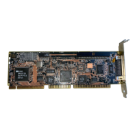
Installing the Adapter
1.
To install the adapter, remove the mounting screw and the existing
bracket from the rear panel behind the selected 32-bit VL slot.
2. Press the
BT-445C
downward into the selected 32-bit VL slot, align the
mounting bracket, and reinstall the mounting screw.
Caution: Make sure that the board is properly seated in the slot.
3.
Connect the
50-pin
SCSI cable to the adapter’s single-ended SCSI con-
nectar,
J3, attaching the other end to the SCSI device. Place the connec-
tor cable around the power supply and over any other boards.
Depending on the configuration of your computer, other types of cables
could be used.
BT-44%
Internal
fqoppy
Internal SCSI Connector
SCSI
Disk
Floppy Drive
Drive
Drive
Connector
II
Systerh
Motherboard
External SCSI
Connector
Figure 2-3.
BT-44%
Installation
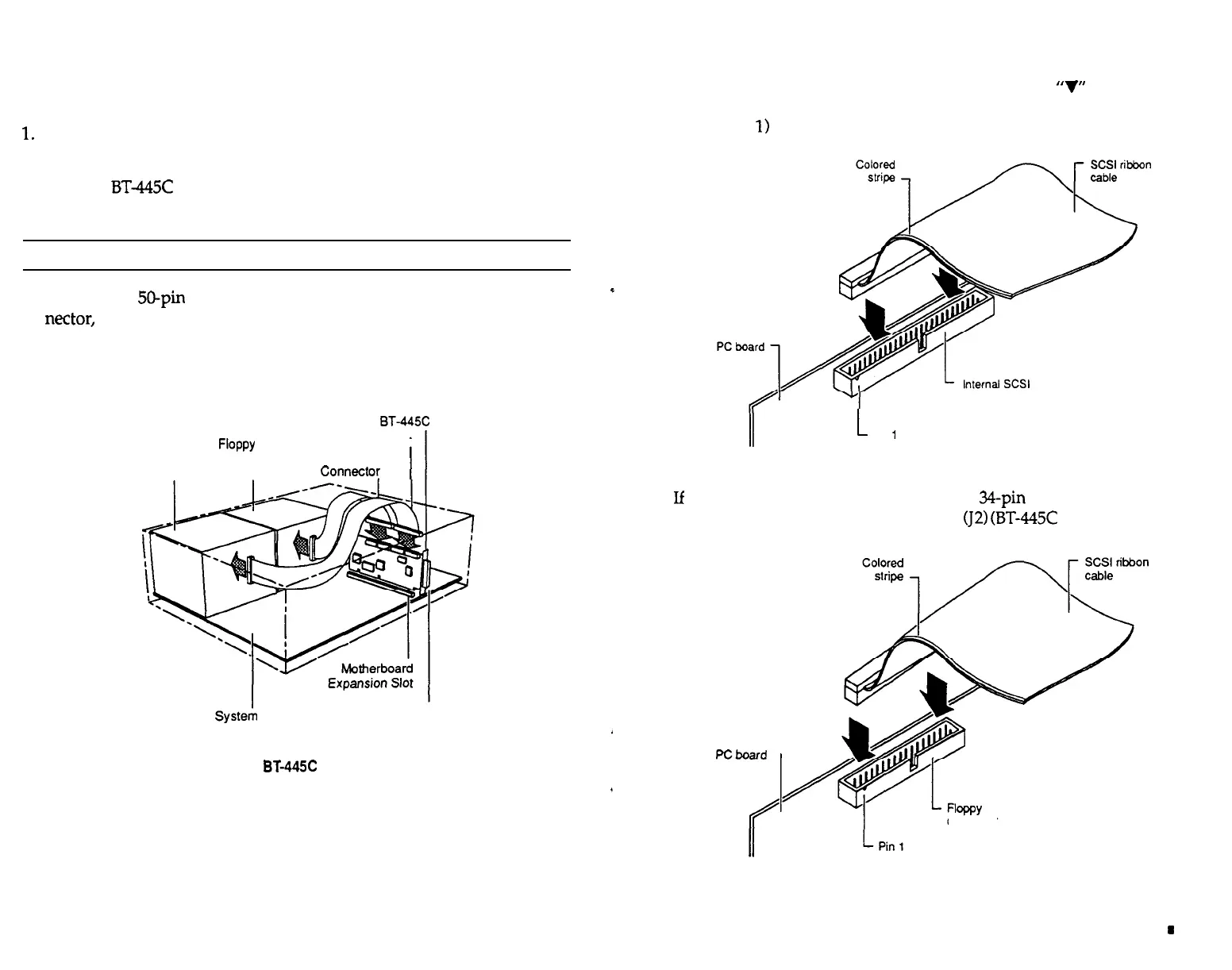
Before plugging in cable connectors, check that the
‘7”
mark molded
on the connector or the colored stripe on the cable (indicating the loca-
tion of Pin
1)
matches Pin 1 of the connector on the BT-445C board.
connector
L
Pin
1
Figure 2-4. SCSI Cable Installation Detail
4.
If
connecting to a floppy drive, insert the
34pin
floppy cable from the
floppy drive into the floppy connector
(J2)
(BT-445C
only).
PCboard
1
/
connector
Figure 2-5. BT-445C Floppy Cable Installation Detail
2-6 n Installation
Installation
m
2-7