Page 16 of 61
INSTRUCTION, USE AND
MAINTENANCE MANUAL
EN
9.2.4 Fitting of external data gauge (stand-
ard on some models)
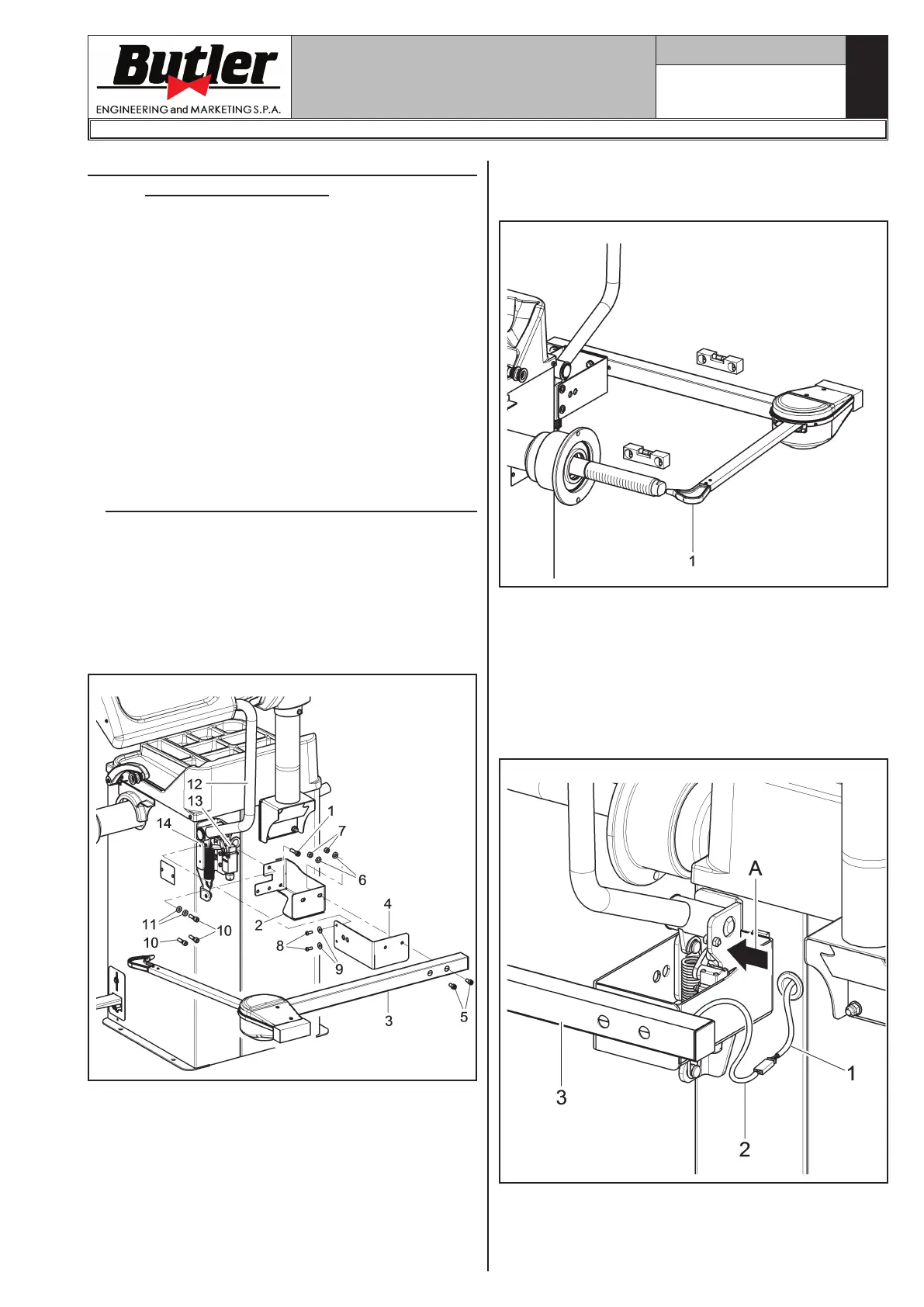
1. Remove the protection guard (Fig. 10 ref. 12), if
already present.
2. Remove the bolts (Fig. 10 ref. 10) and the washers
(Fig. 10 ref. 11) from the wheel cover support, be-
ing very careful about holding the same support.
Insert the gauge bracket (Fig. 10 ref. 2) into the
lateral slot of the wheel cover support (see Fig. 12
ref. A).
3. If necessary, remove the microswitch (Fig. 10
ref. 13) so that it is possible to reach the securing
bolts more easily.
4. Fit the fixing bolt (Fig. 10 ref. 1) and bolts (Fig. 10
ref. 10), previously removed, into the gauge bracket
(Fig. 10 ref. 2); then screw the assembly to the
threaded rivets placed on the rear part of the frame,
without using the previously removed washers
(Fig. 10 ref. 11). Secure bracket (Fig. 10 ref. 4)
to the support guard (Fig. 10 ref. 14) with the bolts
(Fig. 10 ref. 8) and the washers (Fig. 10 ref. 9).
Lock the gauge arm (Fig. 10 ref. 3) to the brackets
(Fig. 10 ref. 2-4) using the 2 bolts (Fig. 10 ref. 5),
the washers (Fig. 10 ref. 6) and the nuts (Fig. 10
ref. 7), so that the shaft and the gauge arm are lev-
elled (see Fig. 11).
Fig. 10
5. Also make sure the gauge tip (Fig. 11 ref. 1) is
positioned APPROXIMATELY at the centre of the
chuck.
Fig. 11
6. Connect connector (Fig. 12 ref. 1) of the cable com-
ing from inside the machine to connector (Fig. 12
ref. 2) of the cable coming from the gauge arm. Fit
the section of the cable with the connectors inside
the arm (Fig. 12 ref. 3).
7. Fasten the cable with clamps.
8. Enable the external data gauge and carry out the
device calibration.
Fig. 12
9. Mount microswitch again (Fig. 10 ref. 13), if previ-
ously removed.
10. Fit the protection guard (Fig. 10 ref. 12), as de-
scribed in Par. 9.3.2..
1296-M024-01
LIBRAK350 - LIBRAK350PRO


 To Next Page