Page 18 of 61
INSTRUCTION, USE AND
MAINTENANCE MANUAL
EN
11.0 FITTING THE WHEEL ON THE
SHAFT
To achieve perfect balancing, the wheel must be care-
fully and properly fitted on the shaft.
Imperfect centring will inevitably cause unbalances.
WHAT IS MOST IMPORTANT IS
THAT ORIGINAL CONES AND
ACCESSORIES, SPECIALLY DE-
SIGNED TO BE EMPLOYED WITH
THE WHEEL BALANCERS, ARE
USED.
Wheel fitting using the cones provided is illustrated
below.
For alternative fittings, using optional accessories, refer
to the special instructions provided separately.
11.1 Wheel assembly
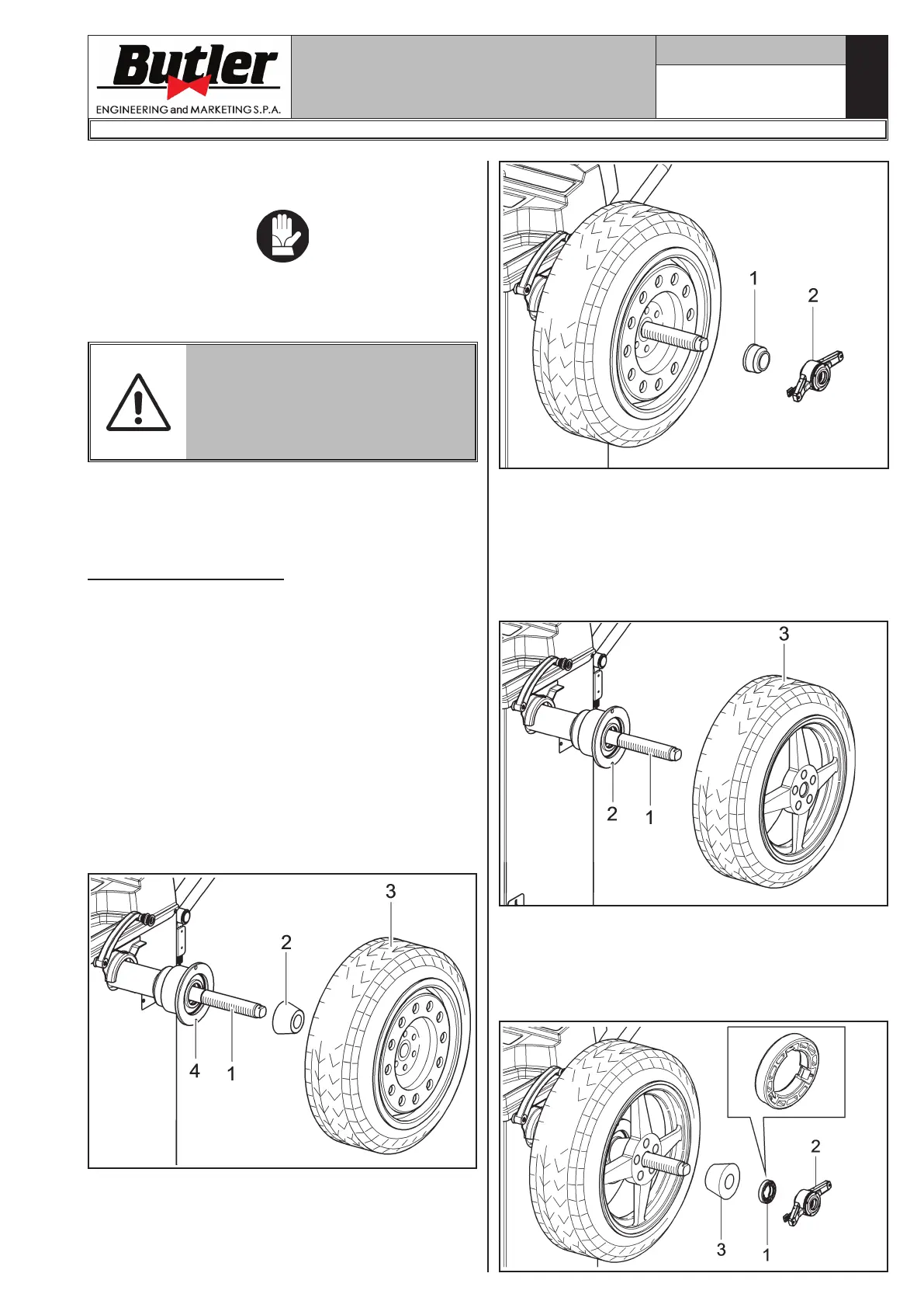
1. Remove any type of foreign body from the wheel
(Fig. 14 ref. 3): already-existing weights, stones
and mud, and make sure the shaft (Fig. 14
ref. 1):and the rim centring area are clean before
fitting the wheel on the shaft.
2. Carefully choose the cone (Fig. 14 ref. 2) most suit-
able for the wheel to be balanced. These accessories
must be selected according to the shape of the rim.
Carefully position the wheel (Fig. 14 ref. 3), fit-
ting the cone (Fig. 14 ref. 2) on the shaft (Fig. 14
ref. 1) (otherwise this could seize) until this rests
against the support flange (Fig. 14 ref. 4).
3. Fit the wheel with the inner side of the rim towards
the wheel balancer and against the cone.
Fig. 14
4. Fit the protection cap (Fig. 15 ref. 1) in the locknut
(Fig. 15 ref. 2) and fasten against the wheel.
Fig. 15
Some aluminium wheels, with very high centring, must
be fitted with the cone outside the wheel.
5. Clean the shaft (Fig. 16 ref. 1) before fitting the
wheel.
6. Fit the wheel (Fig. 16 ref. 3) with the inside of the
rim towards the wheel balancer, until the wheel is
up against the support flange (Fig. 16 ref. 2).
Fig. 16
7. Fit the cone (Fig. 17 ref. 3) with the narrowest part
turned towards the wheel.
8. Fit the pressure ring (Fig. 17 ref. 1) in the nut
(Fig. 17 ref. 2) and fasten the cone (Fig. 17
ref. 3).
Fig. 17
1296-M024-01
LIBRAK350 - LIBRAK350PRO


 To Next Page