GB
Page 22 of 62
INSTRUCTION, USE AND
MAINTENANCE MANUAL
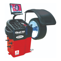
12.3 Ultrasound sensor support adjustment
Ultrasound sensor support (Fig. 28A-B ref. 1) must
be used in the “fully-lowered” position, as shown in
Fig. 28A.
However with wheels with great diameter, you can set
it higher so that the wheel can be mounted easily onto
the mandrel (see Fig. 28B).
In order to carry out the adjustment, just loosen the
handwheel (Fig. 28B ref. 2) and place the support
in the wished position.
At the end tighten the handwheel (Fig. 28B ref. 2).
Fig. 28A
Fig. 28B
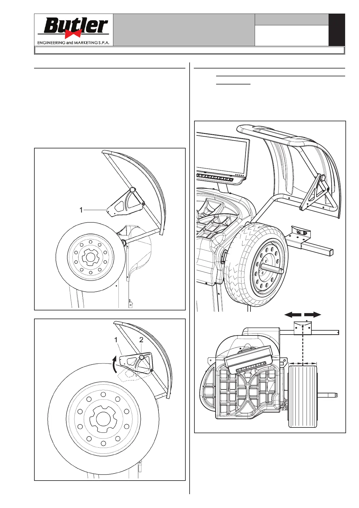
12.4 Correct positioning of the device during
the Run-out detection tyre outer side
(Optional)
To make sure that the rim/tyre “Run-out” detection is
correct, place the device as shown in Fig._29: place
the measurement sensor so that it is turned to the
tyre centre line.
= =
Fig. 29
LIBRAK380.3DTEC - LIBRAK380P.3DTEC - LIBRAK430.3DTEC - LIBRAK430P.3DTEC
1297-M021-1_B
 Loading...