GB
Page 50 of 62
INSTRUCTION, USE AND
MAINTENANCE MANUAL
15.2 Machine calibration
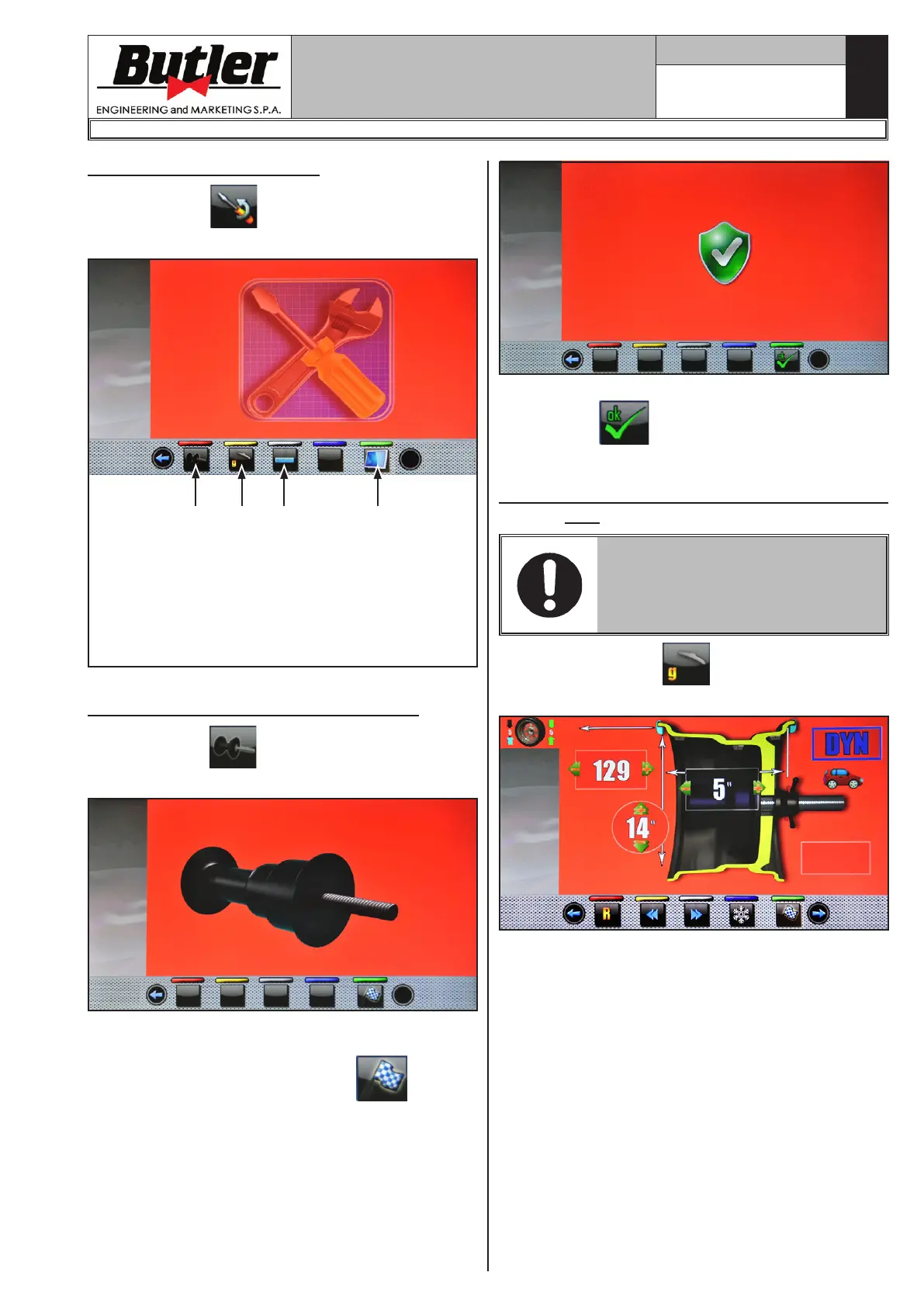
Press the button (Fig. 50 ref. 2) to display the
following screen page on monitor:
1 2 3
KEY
1 – Mandrel “0” (zero) calibration
2 – Weight measurement sensors calibration
3 – Calibration of the width sensor (not enabled)
4 - Touch monitor calibration
3 4
15.2.1 Mandrel “0” (zero) calibration
Press the button to display the following screen
page on the monitor:
After making sure that the mandrel is unloaded (no
wheel or mounted accessories) and in the case of closed
pneumatic mandrel, press the button and close
the guard. The spindle will rotate for a few minutes
until you see the screen below:
At this point the machine has all its measuring fields.
Press button
to return to calibrations screen
page.
15.2.2 Weight measurement sensors calibra-
tion
ASSEMBLE A BALANCED WHEEL
ON THE SPINDLE AND PERFORM
THE SPINDLE “0” CALIBRATION
PROCEDURE DESCRIBED IN PAR.
15.2.1 (WITH WHEEL MOUNTED).
- Press on the button to display the following
screen page:
- Close the protection carter to start the dimensions de-
tecting procedure of the rim mounted on the mandrel
and perform the 1
st
spin of the wheel without weights.
- At the end, on the monitor will appear the following
screen, saying that you should apply a weight of 100
g to the "12 o'clock" outer rim.
LIBRAK380.3DTEC - LIBRAK380P.3DTEC - LIBRAK430.3DTEC - LIBRAK430P.3DTEC
1297-M021-1_B


 To Next Page