GB
Page 12 of 62
INSTRUCTION, USE AND
MAINTENANCE MANUAL
USE THE MACHINE INDOORS OR IN A ROOFED
AREA. PLACE OF INSTALLATION MUST BE
DRY, ADEQUATELY LIT AND IN COMPLIANCE
WITH APPLICABLE SAFETY REGULATIONS.
The location of the machine requires a usable space
as indicated in Fig. 4. The positioning of the machine
must be according to the distances shown. From the
control position the operator is able to observe all the
machine and surrounding area. He must prevent unau-
thorized personnel or objects that could be dangerous
from entering the area.
The machine must be fixed on a flat floor surface,
preferably of cement or tiled. Avoid yielding or irregu-
lar surfaces.
The base floor must be able to support the loads trans-
mitted during operation.
This surface must have a strength of at least 500 kg/m².
The depth of the solid floor must be sufficient to guar-
antee that the anchoring bolts hold.
8.2 Lighting
The machine does not require its own lighting for
normal working operations. However, it must be used
in an adequately lit environment.
In case of poor lighting use lamps having total power
800/1200 Watt.
9.0 MACHINE ASSEMBLY
After having freed the various components from the
packing check that they are complete, and that there
are no anomalies, then comply with the following in-
structions for the assembly of the components making
use of the attached series of illustrations.
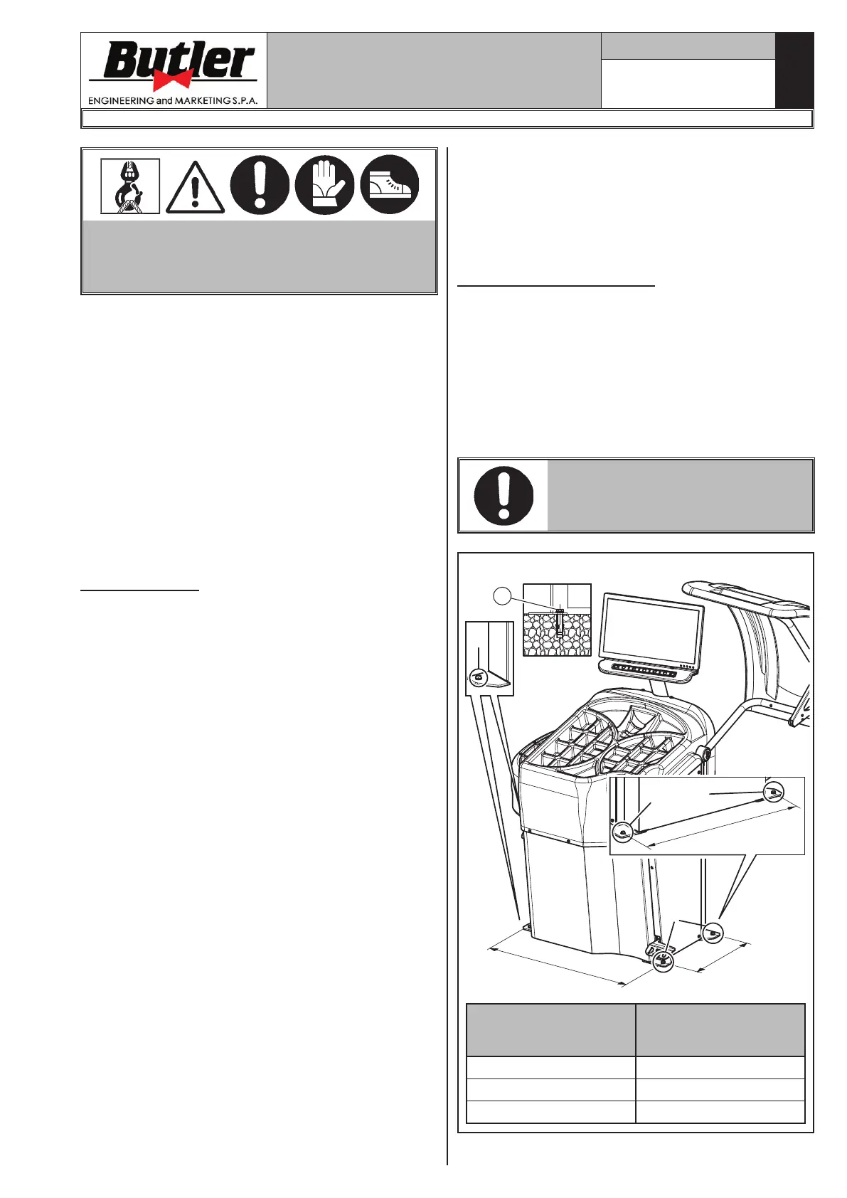
9.1 Anchoring system
The packed machine is fixed to the support pallet
through the holes prearranged on the frame. Such
holes can be used also to fix the machine to the ground,
through floor anchor small blocks (excluded from sup-
ply). Before carrying out the definitive fixing, check that
all the anchor points are laid down flat and correctly
in contact with the fixing surface itself. If not so, insert
shimming profiles between the machine and the fixing
lower surface, as indicated in Fig. 5.
IN CASE OF WHEEL WEIGHING
MORE THAN 30 KG, IT IS COM-
PULSORY TO FIX TO THE GROUND
BY MEANS OF SCREW ANCHORS.
X
b
a
X
1
X
c
X
X
Fig. 5
LIBRAK380.3DTEC
LIBRAK380P.3DTEC
LIBRAK430.3DTEC
LIBRAK430P.3DTEC
a= 374 a= 374
b= 686.5 b= 762
c= 686.5
LIBRAK380.3DTEC - LIBRAK380P.3DTEC - LIBRAK430.3DTEC - LIBRAK430P.3DTEC
1297-M021-1_B


 To Next Page