Water level with
respect to the top
of the pool
Coping
M30
135 mm
Coping
M40
125 mm
Coping
M55
110 mm
200
3,5
49
3,5
Cornière
Fixation des chevilles à 25mm
par rapport à l'arase du bassin
20 cm béton mini
84
40
Ø 54 maxi
19,6
3
6
25
74
16
80
35 mini.
10 maxi
19
20
15 maxi
25
52.6
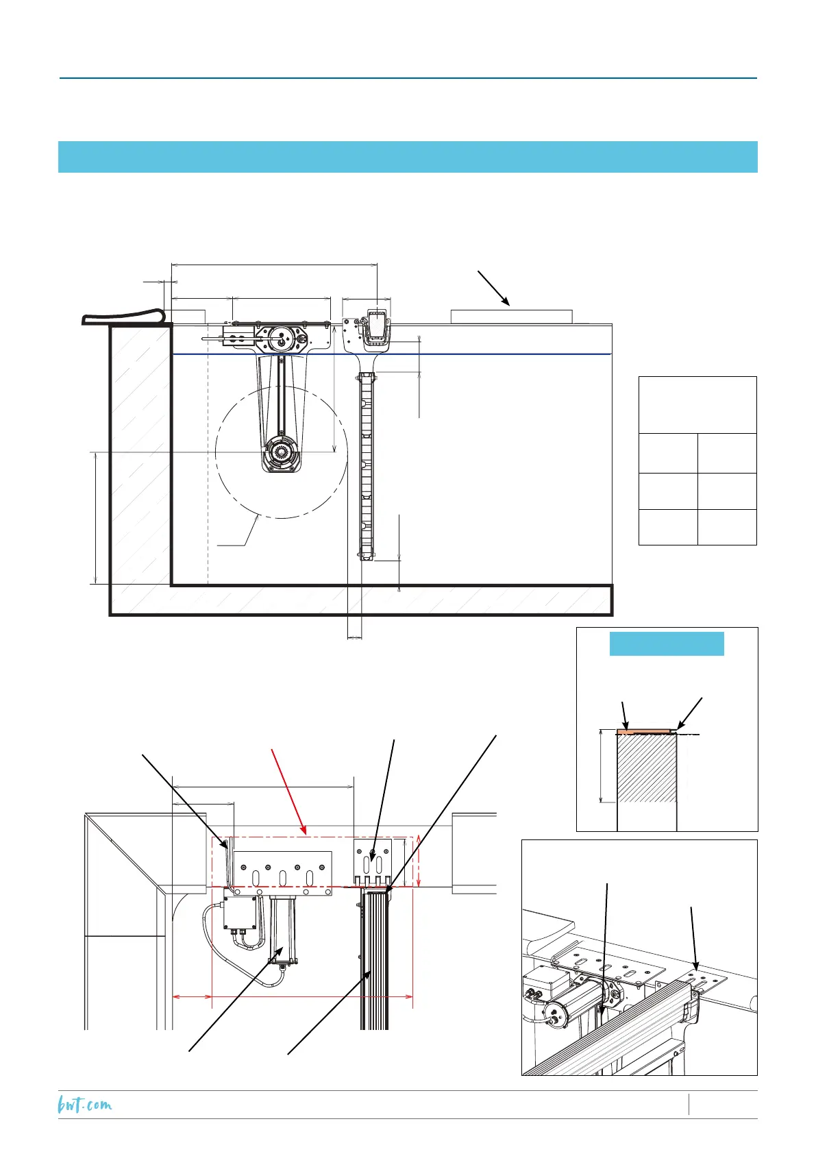
16.1 With PIT WALLS and coverdeck SUB-coping mounting plates
Recess to run
cables
Conguration for rounded angles, radius, 15 cm or broken corners
Sub-coping
mounting plate
Coverdeck beam
housing
Concrete reserve
zone height
20 cm
Coverdeck motor
Coverdeck beam
Coping minimum overhang 22 mm
maximum overhang 35 mm
Water level
83 cm duckboarding
HungResurfacing
Pool
level
Detail, top of the wall
84
40
Ø 54 maxi
19,6
3
6
25
74
16
80
35 mini.
10 maxi
19
20
15 maxi
25
52.6
Sub-coping
mounting plate
Coverdeck
end fixing plate
16. ASSEMBLY DIAGRAMS
**PLEASE NOTE THAT DIMENSIONS ARE QUOTED IN CM, UNLESS OTHERWISE INDICATED**
VERY IMPORTANT
2019/01 - Indice de révision : N - Code : 34201PROTECTION & SÉCURITÉ
53/60