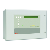
QT601-2 Quantec Controller
Installation & Programming Manual • Approved Document No. DNU6012001 Rev 5 • Page 33 of 42
Checking the Devices
Call Points, Overdoor Lights, Ceiling Pulls, Slave Call Points and Tail Call Leads
• Press the call button on the call point. After a three second delay, the light should pulse rapidly through red, green & orange.
• If the light goes steady red, the call point is already programmed and will confuse the commissioning engineer. It should be reset
by shorting the ‘reset ID’ pins inside with a shorting link. Make sure you do not short the pins to any point on the circuit board as this
will damage the call point and can be factory detected so will not be covered by the warranty. Use a shorting link to short the pins.
Do not use any other device.
• Overdoor lights connected to a call point will exactly follow the pulsing light on the call point (when the orange light shows on the
call point, both red and green will be lit at the overdoor light).
• The red lights on any ceiling pull(s) and/or slave call point(s) will follow the red light on the call point.
• If everything is working okay, press the reset button on the call point twice to return to the passive state.
• Check the continuity of ceiling pulls, slave call points and tail call leads with a multimeter. (You cannot test the correct operation of
these devices prior to commissioning.)
•
Reset the system at the Quantec Controller after testing to ensure all devices are returned to the passive state.
Infrared Ceiling Receivers
• Press the call button inside the ceiling receiver (located on the right hand side of the PCB). After a three second delay, the receiver’s
LED should pulse rapidly through red, green & orange. If the light goes steady red, the ceiling receiver is already programmed and
will confuse the commissioning engineer. Reset using the ‘reset ID’ pins (see above). If everything is working okay, press the reset
button (located on the left hand side of the PCB) twice to return the receiver to the passive state.
Displays
• An unassigned display beeps intermittently, is backlit and shows the unassigned message:
This means that the display has been installed correctly.
• If the display shows the time, it is assigned and should be reset using the ‘reset ID’ pins (see above).
• The call and assist volume level can be adjusted using the control marked ‘volume’. (ATTACK and EMERGENCY calls will always come
through at full volume.)
• The display contrast can be adjusted using the control marked ‘contrast’. If you turn it down too far the display will disappear.
Monitoring Points
• Turn the key to ‘isolate’. The light will flash red and green. Turn back to ‘on’ and press ‘reset’ to clear the lights.
• Ensure the links are correctly fitted for their function (see the device instructions).
Addressable Sounders and Overdoor Lights
• Check that the network voltage of the system stands at 16-17 V by placing a multimeter across the input terminals of these devices.
(You cannot test the correct operation of these devices prior to commissioning.)
General
• If any single device does not work, swap it with a device that does work elsewhere on the network. If the fault moves with the
device, you probably have a faulty device. If the new device shows the same fault as the one you have moved, you probably have a
wiring fault.
Finishing Pre-Commissioning
• When you have successfully completed all of the above checks, power the system down. Any limbs with faults still present should
be disconnected and relevant information left for the commissioning engineer. Pre-commissioning is now complete.
Note: Any limbs left with faults on may require extra visits by the commissioning engineer and extra cost may be incurred.
Things the Commissioning Engineer will Need
• A set of plans suitable for marking up.
• Information from the client about the naming of each room. If this is not available the commissioning engineer will set the system
up as he thinks best and there may be a charge for altering the system at a later date should this be required.
• Information from the client about the routing of calls (Areas & Groups) – if possible.
• Quantec Main manual (this document) including programming sheets.
• Individual instruction supplied with each device.
• Pre-Commissioning Certificate signed by the installation contractor.
UNASSIGNED
Accept to ASSIGN

 Loading...