E-5cab Produkttechnik GmbH & Co KG
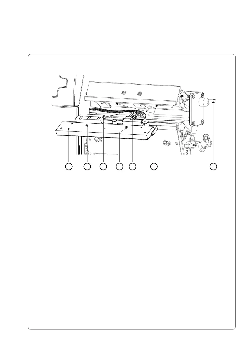
4. To lift the printhead assembly, swing the lever (2) clockwise until it stops.
5. Remove the printhead (3) from the pins (8) on the printhead carriage.
6. Carefully unplug the printhead (4) from the connectors of the printhead
cables (6 and 7).
7. Connect the new printhead to the cables.
8. Place the printhead into the assembly and insert the holes (5) onto the
pins (8).
9. Tighten the locking screws (1) by hand. Check that the printhead is
completely secured in the printhead carriage.
10. Swing the lever (2) again into the position shown in figure E-4.
11. Tighten the locking screws (1) completely. Do not over-tighten the locking
screws (1).
Fig. E-5 Changing Printhead A6 (II)
25 563 7 8
Appendix E - Replacing Assembly Units
 Loading...