98 2 Installation
2.3.2 Connecting to the External Control
for devices with peripheral port only
The peripheral port allows to control the device in a network.
1. Check that the device is switched off.
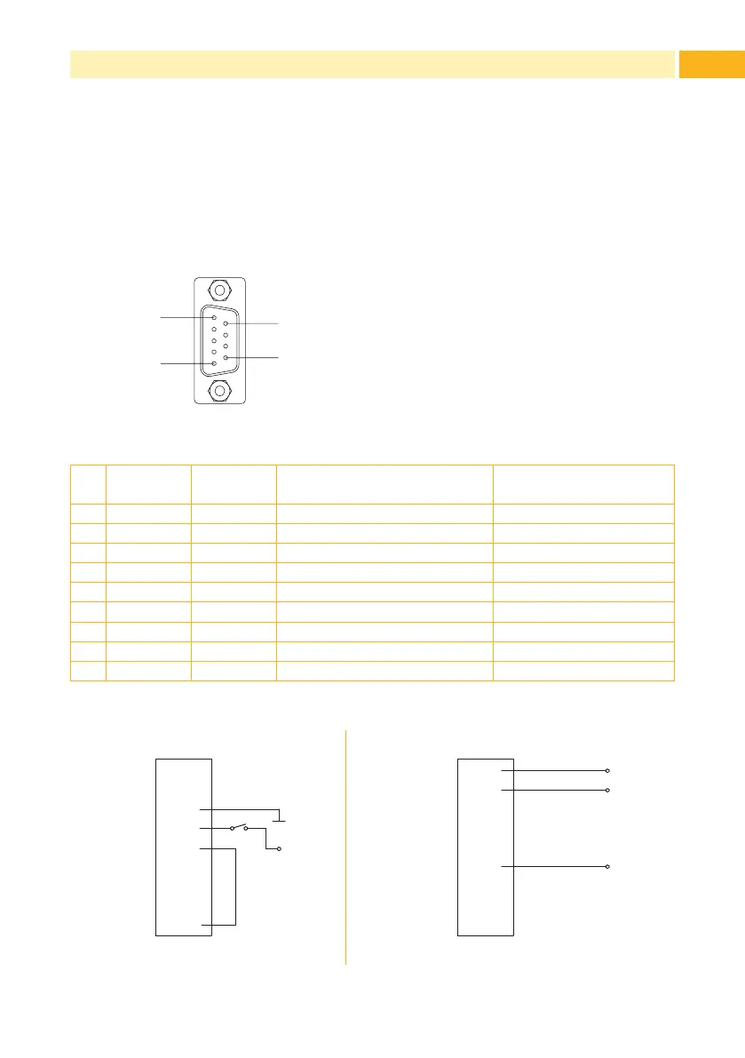
2. Connect the external control to the 9 pin SUB-D connector of the
peripheral port (3 / Fig. 3):
Pin5
Pin1
Pin9
Pin6
Fig. 4 Peripheral port
Pin Signal Direction Function Activation /
Active state
1 ERROR Output Error 0V at Pin
2 ESP Output Label in peel position +24V at Pin
3 EXTGND (Input) External ground (0V)
4 STRT Input Start Switch on +24V
5 EXTAN Input Evaluation STRT Connect with Pin 9 !!!
6 EXT24P (Input) External voltage 24V
7 - - do not use
8 - - do not use
9 INTGND (Output) Internal ground (0V)
Table 1 Pin assignment of the peripheral port
1
2
3
4
5
6
7
8
9
ERROR
ESP
EXTGND
STRT
EXTAN
EXT24P
-
-
INTGND
24P
GND
Pin
1
2
3
4
5
6
7
8
9
ERROR
ESP
EXTGND
STRT
EXTAN
EXT24P
-
-
INTGND
24P
Pin
ERROR
ESP
Imax = 50 mA
STRT ERROR, ESP
Fig. 5 External minimum circuit