17
4 Replacing Assembly Units
4.6 Replacing the CPU
Danger!
Risk of death via electric shock!
Before opening the rear cover, disconnect the device from the mains supply and wait at lease one
minute until the power supply unit has discharged.
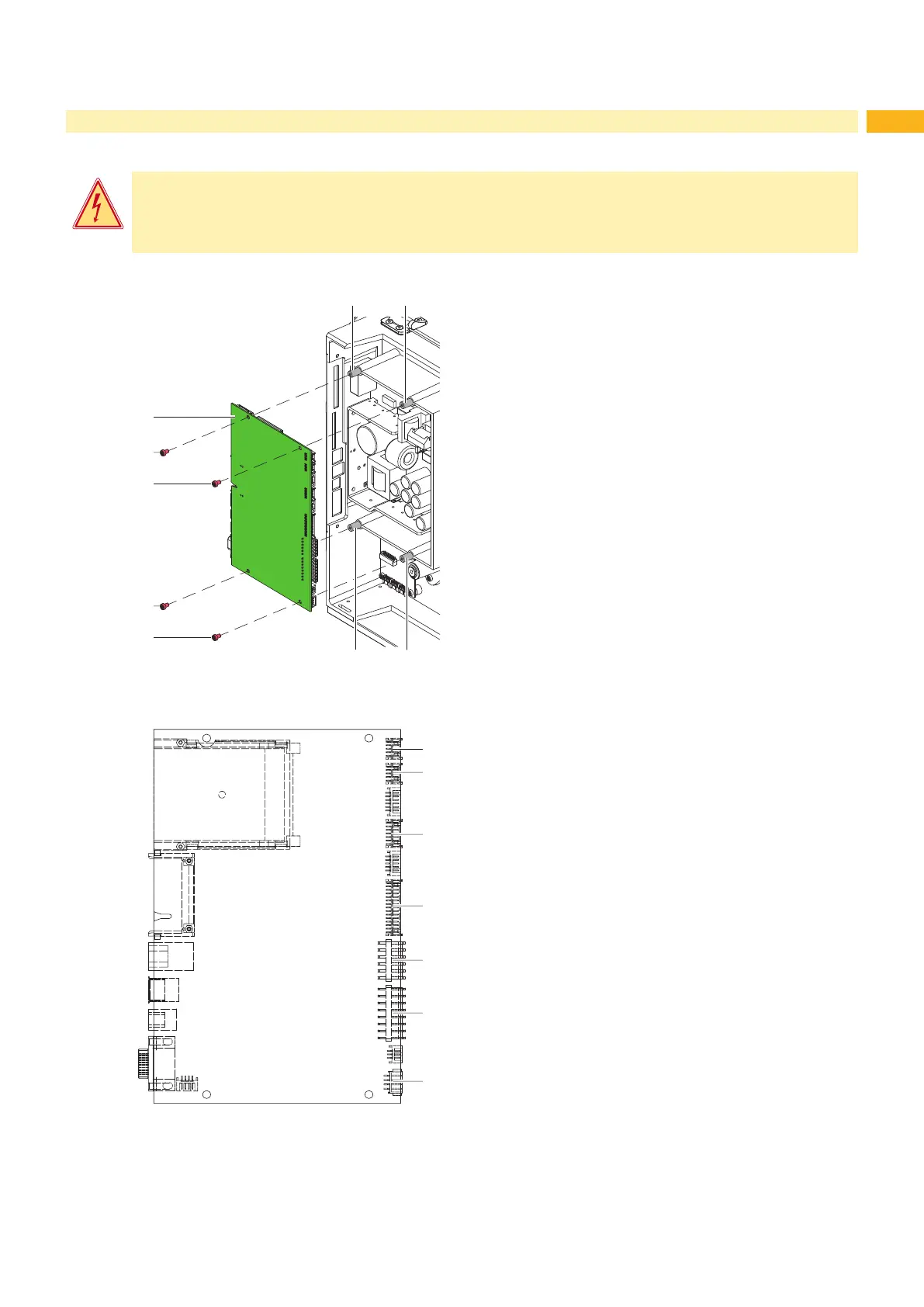
1
2
2
2
2
3 3
3 3
Removing the CPU
1. If possible, save the printer conguration to a Compact-
Flash card Conguration Manual.
2. Unplug the printer from the electrical outlet.
3. Detach all interface cables from the back of the printer.
4. Remove all memory cards from the slots.
5. Remove the rear cover. 2.2 auf Seite 6.
6. Unplug all side plug connections from the CPU (1).
7. Remove the four xing screws (2) from the CPU.
8. Remove the CPU.
Installing the CPU
1. Place CPU (1) onto the retainers (3).
2. Secure the PCB with four screws (2).
3. Insert all plug connections on the PCB.
4. Install the rear cover.
5. Restore all interface connections on the back of the
printer.
6. Connect the power cable at the rear of the printer.
7. Update the rmware if necessary.
8. Adjust the label sensor Conguration Manual.
9. Load the printer conguration from the memory card if
possible. Otherwise, set the printer conguration via the
control panel Conguration Manual.
4 Control panel
5 Peripheral port
6 Sensors
7 Printhead signals
8 Printhead power supply
9 Power supply unit
10 Stepper motor
Fig. 15 Replacing the CPU
4
5
6
7
8
9
10
Fig. 16 Used connectors on the CPU
 Loading...